
Bend type spiral flow generator

A generator and spiral flow technology, applied in pipeline systems, mechanical equipment, gas/liquid distribution and storage, etc., can solve the problems of unsatisfactory operation effect, inability to meet requirements, complex device structure, etc., and achieve novel structure and spiral strength. Large, spiral effect good effect

Inactive Publication Date: 2015-07-22
长江(扬中)电脱盐设备有限公司
View PDF6 Cites 0 Cited by
  • Summary
  • Abstract
  • Description
  • Claims
  • Application Information

AI Technical Summary

Problems solved by technology

But its disadvantage is that the structure is complicated, and frequent maintenance is required to ensure the position parameters of the nozzle (Chigier N.A, Chervinsky A. Experimental investigation of swirling vortex motion in jets. Transactions of ASME, Journal of Applied Mechanics, 1967, Vol.34, 443-451 .and Sjparrow E.M, Chaboki A. Swirl-affected turbulent fluid flow and heat transfer in a circular tube. Transactions of ASME, Journal of Heat Transfer, 1984, Vol.106, 766-773.)
Professor Kiyoshi Horii of Baiyuri Women's University in Japan proposed a self-generated spiral flow generator (such as figure 1 As shown), the inventor uses air as the flow medium, and under the conditions of Reynolds numbers of 1.0×10⁵ and 1.6×10⁵, the inflow mode of radial injection through the small hole in the axisymmetric plane is displayed by particles The existence of spiral flow, and obtained French patent (No.0456931) and U.S. patent (No.4721126), but this device structure is complex, energy consumption is higher, and actual operation effect is not ideal (Horii, K, Matsumae, Y ., Cheng, X.M., Takei, M. and Hashimoto, B.A Study of Spiral Flow (Part3), Opening and Orientation Contral of Fiber by Spiral Flow, Trans.Japan Soc.Aero.Space Sci., 1990a, 32(98))
Therefore, the above method cannot satisfy the requirement

Method used


Image

  • Bend type spiral flow generator
  • Bend type spiral flow generator
  • Bend type spiral flow generator

Examples


Embodiment Construction

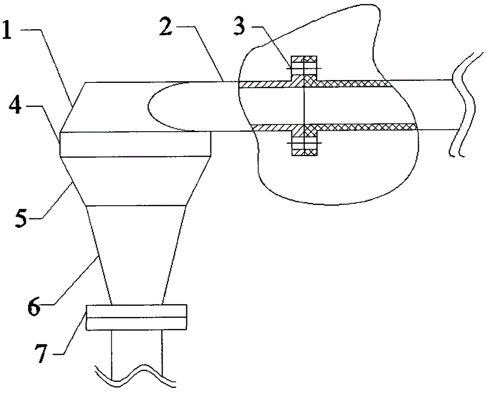
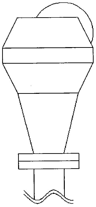
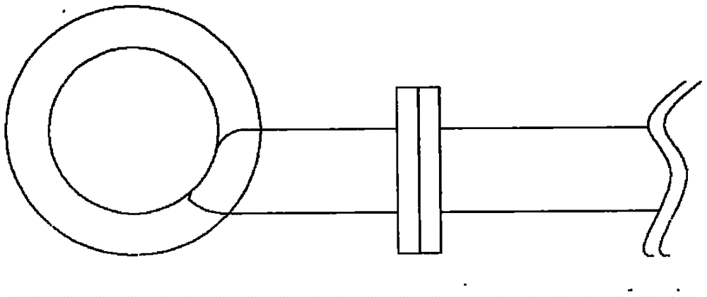
[0019] Such as figure 1 , 2 , shown in 3, the present invention is made up of three parts of inlet pipe (2), simplified body and outlet pipe. The inlet pipe (2) and the outlet pipe respectively include an inlet flange (3) and an outlet flange (7) to facilitate connection with external pipelines. Wherein, the simplified body is made up of three parts of a frustum-shaped barrel (1), a cylindrical barrel (4) and a conical barrel. The conical barrel includes a large cone section (5) and a small cone section (6). When installing, directly install the device as a whole on the experimental pipe section or in the actual engineering pipe section. The spiral effect is obvious and easy to install.


PUM


Abstract

The invention discloses a bend type flow generator. The generator is mainly composed of an inlet pipe (2), a cylinder and an outlet pipe; and the inlet pipe (2) and the outlet pipe each comprise an inlet flange (3) and an outlet flange (7), and therefore the inlet pipe and the outlet pipe can be conveniently connected with an external pipeline. The cylinder is composed of a truncated-cone-shaped cylinder body (1), a cylindrical cylinder body (4) and a conical cylinder body, wherein the conical cylinder body comprises a large conical segment (5) and a small conical segment (6); the cylinder is a main component generating the spiral flow, and fluid from the inlet pipe tangently enters along the inner wall of the truncated-cone-shaped cylinder body, and the obvious tangential speed can be generated; due to the fact that the direction of the outlet pipe is perpendicular to the inlet flow direction, and due to the downward drainage effect of the cylindrical cylinder body and the conical cylinder body, the fluid can flow out of the outlet pipe in a high spiral flow manner. Finally, due to the effect of the large conical segment and the small conical segment in the conical cylinder body, the flow speed of the fluid is further improved, and the spiral effect is further strengthened.

Description

technical field [0001] The invention belongs to a fluid spiral generating device and a pipeline fluid conveying device, in particular to an elbow type spiral flow generator, which has an extremely wide application range in industry, and has applications in hydraulic engineering and mechanical processing. technical background [0002] Spiral flow is a flow form with a rotating flow field. It has a wide range of industrial applications, including hydraulic engineering and mechanical processing. At the same time, spiral flow technology has also entered the field of people's daily life, such as spiral flow energy-saving gas stoves. Since spiral flow has such a wide range of applications, the conditions for its generation are very critical. Generally speaking, there are three conventional methods for generating spiral flow: tangential flow, installation of deflectors, and rotating pipes (this method is not common). [0003] The tube-type nozzle can generate spiral flow, that is...

Claims


Application Information

Patent Timeline
Patent Type & Authority Applications(China)
IPC IPC(8): F17D1/20
Inventor 李泓韦伟王树立周诗岽
Owner 长江(扬中)电脱盐设备有限公司
Learn More