Dehumidification device

A technology of dehumidification part and wind direction change plate, which is applied in the directions of household heating, lighting and heating equipment, space heating and ventilation, etc., can solve the problems of small wind speed and uneven wind speed distribution in the central part, and achieve uniform wind speed distribution. The effect of expanding the air supply range

Active Publication Date: 2015-07-22
PANASONIC INTELLECTUAL PROPERTY MANAGEMENT CO LTD
View PDF6 Cites 9 Cited by
  • Summary
  • Abstract
  • Description
  • Claims
  • Application Information

AI Technical Summary

Problems solved by technology

However, on the other hand, supplying air only in the direction of width expansion will cause the wind speed in the center to become smaller and the wind speed distribution to be uneven

Method used


Image

  • Dehumidification device
  • Dehumidification device
  • Dehumidification device

Examples


Embodiment Construction

[0020] Hereinafter, embodiments of the present invention will be described with reference to the drawings.

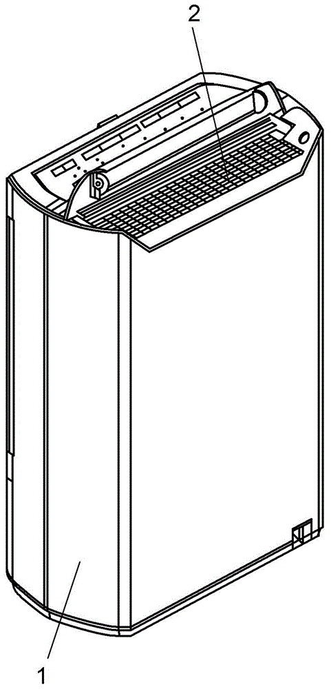
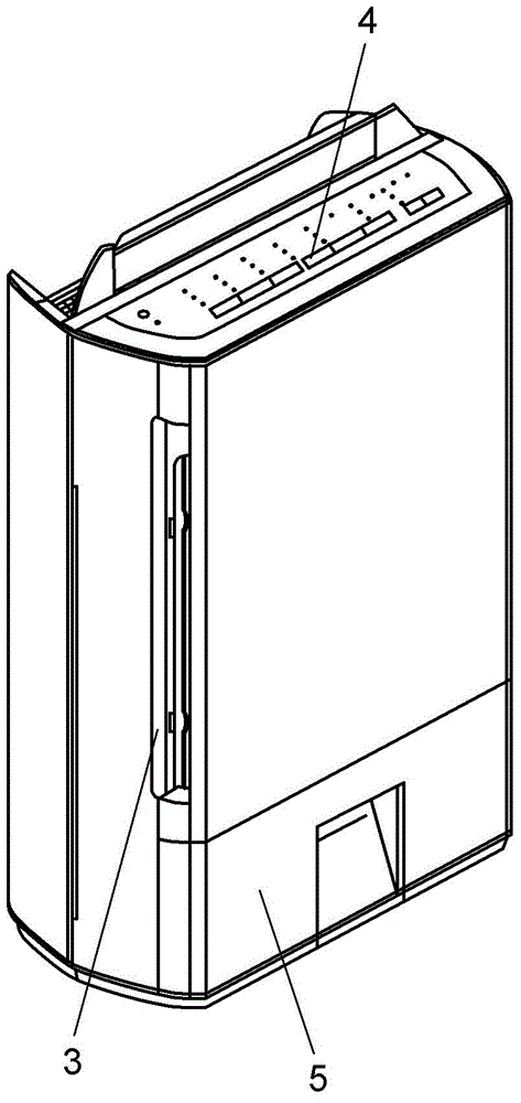
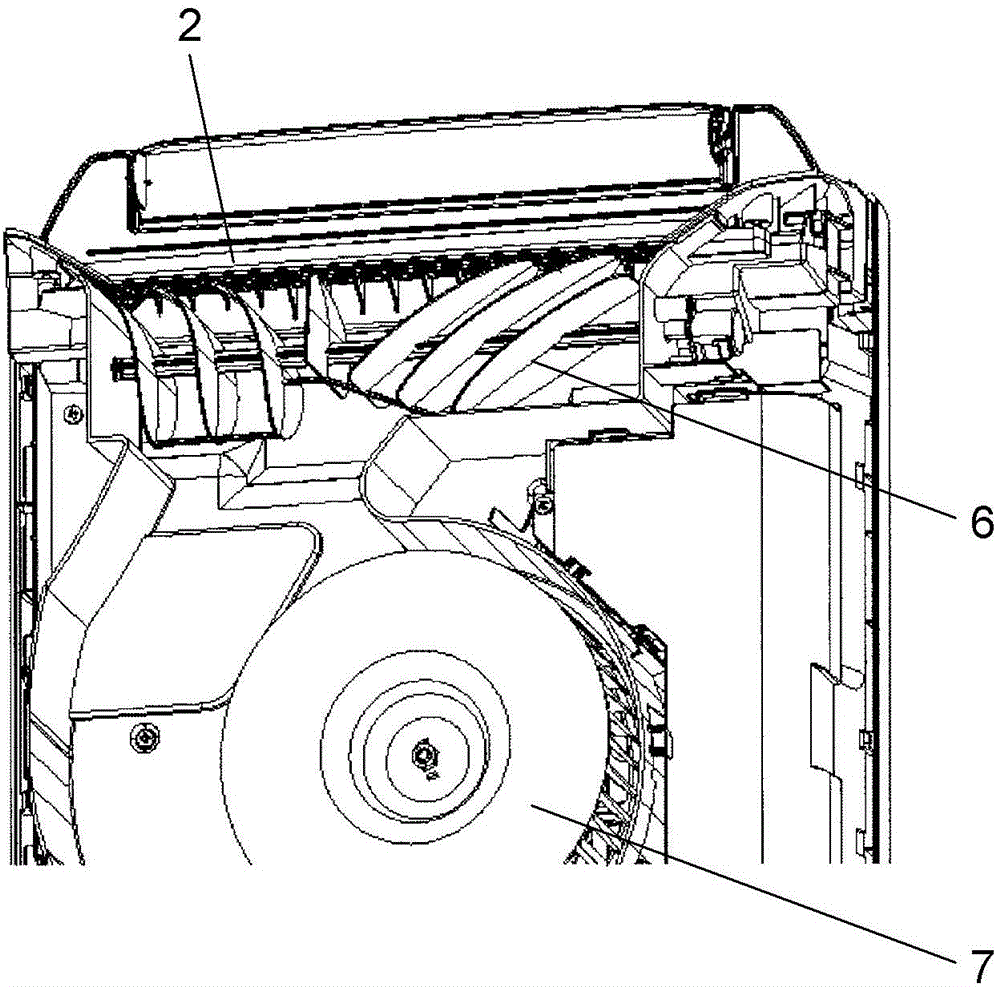
[0021] figure 1 It is an external perspective view of an embodiment of the present invention. figure 2 It is a perspective view of the appearance of the dehumidifier. The main body casing 1 of the dehumidifier is in the shape of a box. The main body case 1 has a substantially rectangular air outlet 2 at the top and an air inlet 3 at the side. In addition, the main body case 1 has a tank body (tank) 5 in the lower part. Moreover, the main body case 1 has an operation part 4 on the upper part. The user operates the operation unit 4 to operate the dehumidifier. As a result, the humid air in the room is sucked in from the suction port 3, and the dehumidifying part ( figure 1 (not shown in the figure) is dehumidified, and the dry air is returned to the room from the outlet 2. The moisture obtained by dehumidification becomes water droplets and is stored in the tank b...


PUM


Abstract

A dehumidification device comprises a dehumidification part disposed in a main body shell provided with a blowout port in a substantially rectangular shape, a wind sending part and a wind direction changing unit (6) changing a wind sending direction of air sent by the wind sending part. The wind direction changing unit (6) comprises a plurality of wind direction changing plates (16) which are disposed at the blowout port and change the wind sending direction of the wind sending part, and a rotary shaft (15) capable of rotationally and fixedly support the wind direction changing plates (16). The rotary shaft (15) extends in the length direction of the blowout port, and the wind direction changing plates (16) are installed in a tilt manner relative to the blowout direction blown out from the blowout port, so the wind sending direction expands in the length direction of the blowout port. At the wind direction changing plates (16) located near the center of the length direction of the blowout port, a gap portion (20) is disposed at the upstream side in the wind sending direction.

Description

technical field [0001] The present invention relates to a dehumidifier that sucks in indoor air and sends out dehumidified air. Background technique [0002] Conventional dehumidifiers are provided with wind direction changing means at the air outlet. The wind direction changing unit rotates a member on which a plurality of wind direction changing plates are mounted on a rotatable shaft, thereby changing the blowing range of the dry air according to various drying conditions of clothes. Thereby, drying unevenness and reduction of clothes drying time can be aimed at (for example, refer patent document 1). [0003] The problem of the conventional dehumidifier is to further expand the blowing range and to make the wind velocity distribution uniform within the blowing range. [0004] That is, recently, there is an increasing demand for drying laundry indoors by using a dehumidifier or the like, that is, so-called indoor drying. The use of a dehumidifier that blows air to the ...

Claims


Application Information

Patent Timeline
Patent Type & Authority Applications(China)
IPC IPC(8): F24F1/02F24F13/15
CPCF24F1/02F24F3/14F24F13/15F24F2003/144
Inventor 藤井泰树田中广宣下田博树
Owner PANASONIC INTELLECTUAL PROPERTY MANAGEMENT CO LTD
Why Eureka
Try Eureka