Light guiding plate, backlight module and liquid crystal display

A technology of light guide plate and light emitting surface, applied in the directions of light guide, optics, instruments, etc., can solve the problems of the narrow frame design and large area of ​​the backlight module, which is unfavorable, and achieves the effect of easy narrow frame design and improved color gamut.

Inactive Publication Date: 2015-07-22
WUHAN CHINA STAR OPTOELECTRONICS TECH CO LTD
11 Cites 12 Cited by

AI-Extracted Technical Summary

Problems solved by technology

However, in figure 1 In the shown backlight module of the prior art, the quantum dot film 30 is used to improve the color gamut of the display backlight provided by the backlight modu...

Method used

[0029] Several light-emitting quantum dots 231 are filled in the groove 2211. A sealing membrane 240 is covered on the top surface of the plate body 221 , so as to seal the light-emitting quantum dots 231 in the grooves 2211 . In this embodiment, the sealing membrane 240 is a transparent membrane. In this way, these luminescent quantum dots 231 filled in the grooves 2211 formed on the top surface of the flat body 221 can improve the color gamut of the display backlight, and at the same time, it is consistent with the surrounding quantum dot film 30 in the prior art shown in FIG. Compared with the area occupied by the quantum dot film failure area 50 , the surrounding sidewalls around the groove 2211 can be thinned to the greatest extent, so that the narrow frame design of the backlight module 100 is easy to realize.
[0030] Several optical films 250 are sequentially arrange...

Abstract

The invention discloses a light guiding plate. The light guiding plate comprises a bottom surface and a light exiting surface, wherein the light exiting surface is opposite to the bottom surface and is recessed to form a groove (2211); the groove (2211) is filled with a plurality of luminous quantum dots (231); and a closing diaphragm (240) covers the light exiting surface so that the luminous quantum dots (231) are sealed in the groove (2211). The invention also discloses a backlight module with the light guiding plate and a liquid crystal display with the backlight module. The groove is formed in the light exiting surface of the light guiding plate and is filled with the luminous quantum dots (231), the color gamut of display backlight can be increased by the luminous quantum dots (231), the luminous quantum dots (231) surround side walls of the periphery of the groove, so that the light guiding plate can be thinned to the maximum extent, and a narrow frame design of the backlight module is easy to implement.

Application Domain

Light guides with fluorescent dopantsPlanar/plate-like light guides +1

Technology Topic

Image

  • Light guiding plate, backlight module and liquid crystal display
  • Light guiding plate, backlight module and liquid crystal display
  • Light guiding plate, backlight module and liquid crystal display

Examples

  • Experimental program(1)

Example Embodiment

[0021] Hereinafter, embodiments of the present invention will be described in detail with reference to the accompanying drawings. This invention may, however, be embodied in many different forms and should not be construed as limited to the specific embodiments set forth herein. Rather, the embodiments are provided to explain the principles of the invention and its practical application, thereby enabling others skilled in the art to understand the invention for various embodiments and with various modifications as are suited to particular intended uses. In the drawings, the thicknesses of layers and regions are exaggerated for clarity of devices, and the same reference numerals will be used to refer to the same elements throughout the specification and drawings.
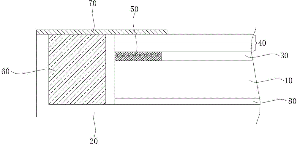
[0022] figure 2 is a side view of a liquid crystal display according to an embodiment of the present invention.
[0023] refer to figure 2 A liquid crystal display according to an embodiment of the present invention includes a liquid crystal panel 100 and a backlight module 200 disposed opposite to each other, wherein the backlight module 200 provides a high color gamut display backlight to the liquid crystal panel 100 so that the liquid crystal panel 100 displays images. In this embodiment, since the gist of the present invention is directed at the backlight module 200, the specific structure of the liquid crystal panel 100 will not be described in detail here to avoid redundant descriptions. Those skilled in the art may refer to the liquid crystal panel disclosed in the prior art. The structure of the panel.
[0024] The backlight module 200 according to the embodiment of the present invention will be described in detail below. image 3 is a partial side view of a backlight module according to an embodiment of the present invention. Figure 4 is a schematic perspective view of a light guide plate according to an embodiment of the present invention.
[0025] together with reference image 3 and Figure 4 , the backlight module 200 according to the embodiment of the present invention includes a back frame 210, a light guide plate 220, a number of light-emitting quantum dots 231, a sealing film 240, a number of optical films 250, a plastic frame 260, a light-shielding double-sided adhesive tape 270 and a reflective sheet 280 .
[0026] Specifically, in image 3 In the figure, only the bottom plate 211 included in the back frame 210 and the side plate 212 located on one side of the bottom plate 211 are shown. It should be understood that the back frame 210 generally includes a bottom plate 211 and four side plates 212 respectively located on four sides of the bottom plate 211 .
[0027] The light guide plate 220 is disposed on the bottom plate 211 of the back frame 210 . In this example, if Figure 4 As shown, the light guide plate 220 includes a flat body 221 and a wedge-shaped body 222 extending upward along one end of the flat body 221 . The thicker end surface of the wedge 222 is usually the light incident end surface, and the thinner end surface of the wedge 222 is smoothly connected with one end of the flat body 221 .
[0028] Further, in this embodiment, the bottom surface of the light guide plate 220 includes the bottom surface of the wedge body 222 and the bottom surface of the flat body 221, and the light output surface of the light guide plate 220 includes the top surface of the flat body 221, the bottom surface of the light guide plate 220 and the bottom surface of the light guide plate The light-emitting surface of 220 is opposite. A portion of the top surface of the flat body 221 is recessed to form a groove 2211 .
[0029] Several light-emitting quantum dots 231 are filled in the groove 2211 . A sealing membrane 240 is covered on the top surface of the plate body 221 , so as to seal the light-emitting quantum dots 231 in the grooves 2211 . In this embodiment, the sealing membrane 240 is a transparent membrane. In this way, these light-emitting quantum dots 231 filled in the grooves 2211 formed on the top surface of the flat body 221 can improve the color gamut of the display backlight, and at the same time figure 1 Compared with the area occupied by the quantum dot film failure region 50 surrounding the quantum dot film 30 in the prior art shown, the surrounding sidewalls surrounding the groove 2211 can be thinned to the greatest extent, so that the backlight module 100 Narrow bezel design is easy to implement.
[0030] Several optical films 250 are sequentially disposed on the sealing film 240 . In this embodiment, these optical films 250 may include brightness enhancement films, diffusion films, etc., which can improve the optical quality of the light source backlight emitted by the sealing film 240. image 3 In , two optical films 250 are shown, but the present invention is not limited thereto. The plastic frame 260 is disposed in the back frame 210 and surrounds the light guide plate 220 , and several optical films 250 are fixed on the plastic frame 260 by light-shielding double-sided adhesive tape 270 , thereby also fixing the light guide plate 220 in the back frame 210 . The reflective sheet 280 is disposed between the light guide plate 220 and the bottom plate 211 of the back frame 210 , and the reflective sheet 280 can reflect the light reaching it back into the light guide plate 220 , thereby improving light utilization efficiency.
[0031] Further, the groove 2211 is filled with transparent glue 290 , and several light-emitting quantum dots 231 are uniformly dispersed in the transparent glue 290 . In this embodiment, preferably, the transparent glue 290 is an ultraviolet curing glue, but the present invention is not limited thereto. In addition, in this embodiment, preferably, the refractive index of the transparent glue 290 is the same or consistent with that of the light guide plate 220 .
[0032] In order to allow the backlight of the light source to diffuse evenly, the groove 2211 is also filled with a number of scattering particles 232 , and these scattering particles 232 and a number of luminescent quantum dots 231 are evenly dispersed in the transparent glue 290 . Further, the heat dissipation particles 232 are transparent particles whose refractive index is different from or inconsistent with that of the transparent glue.
[0033] While the invention has been shown and described with reference to particular embodiments, it will be understood by those skilled in the art that changes may be made in the form and scope thereof without departing from the spirit and scope of the invention as defined by the claims and their equivalents. Various changes in details.

PUM

no PUM

Description & Claims & Application Information

We can also present the details of the Description, Claims and Application information to help users get a comprehensive understanding of the technical details of the patent, such as background art, summary of invention, brief description of drawings, description of embodiments, and other original content. On the other hand, users can also determine the specific scope of protection of the technology through the list of claims; as well as understand the changes in the life cycle of the technology with the presentation of the patent timeline. Login to view more.

Similar technology patents

Special low-dry-fading wide-color-gamut fluorescent ink for 10-micron frequency modulation screen

ActiveCN106497216AImprove wettability and dispersibilityImprove color gamutInksFluorescenceEngineering
Owner:上海数印智能科技股份有限公司

Backlight module and display device

ActiveCN108957857AIncrease the brightness of red lightImprove color gamutNon-linear opticsOptoelectronicsRed light
Owner:TCL CHINA STAR OPTOELECTRONICS TECH CO LTD

Classification and recommendation of technical efficacy words

Why Eureka
Try Eureka