Twisting structure for connecting ultrasonic knife and its ultrasonic knife

A technology of ultrasonic knife and knife holder, applied in the field of medical equipment, can solve the problems of wrench pollution, easy loss, inconvenience of ultrasonic knife, etc., and achieve the effect of ensuring normal connection, not easy to make mistakes, and easy to use.

Active Publication Date: 2017-08-08
MICONVEY TECH CO LTD
View PDF5 Cites 0 Cited by
  • Summary
  • Abstract
  • Description
  • Claims
  • Application Information

AI Technical Summary

Problems solved by technology

[0002] In the application technology of the ultrasonic knife, because the knife head and the transducer are of separate structure, the two are connected through a threaded joint. During the connection process, they need to be fastened together to work normally. Torque wrench, this wrench must be installed and removed through the front end of the instrument, which is inconvenient to operate; and the wrench is relatively small and easy to lose during disinfection in the operating room; due to inadequate training and other reasons, doctors often forget this wrench and may drop it on the ground , and then it needs to be used again, but the wrench that fell on the ground has been polluted, and if it is not sterilized, it will contaminate the equipment and cannot be used; it makes the ultrasonic scalpel unable to work and causes inconvenience

Method used


Image

  • Twisting structure for connecting ultrasonic knife and its ultrasonic knife
  • Twisting structure for connecting ultrasonic knife and its ultrasonic knife
  • Twisting structure for connecting ultrasonic knife and its ultrasonic knife

Examples


Embodiment

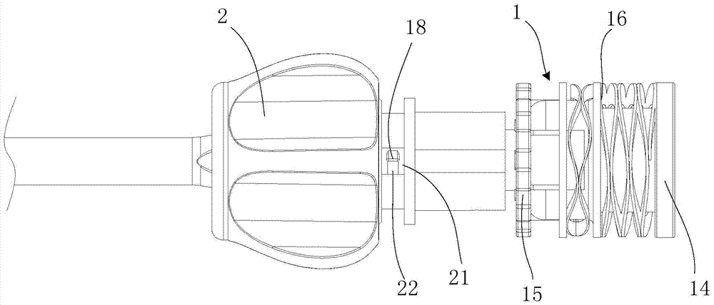
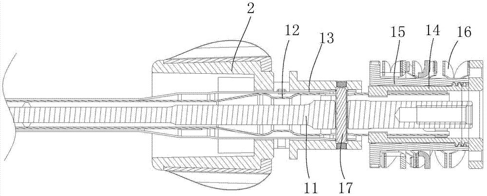
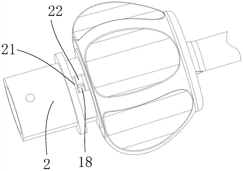
[0040] Such as Figure 1 to Figure 4 As shown, the present invention provides a twisting structure for ultrasonic scalpel connection, including a knife bar assembly 1 and a knob body 2 sleeved outside the knife bar assembly 1. In this example, the knife bar assembly 1 includes an inner sleeve 12 and The connecting head 14 connected to the rear of the inner sleeve 12, the inner sleeve 12 is set outside the ultrasonic action rod 11, the inner sleeve 12 is covered with an outer sleeve 13, and the inner sleeve 12 and the ultrasonic action rod 11 are respectively connected with a shear head, The same pin 17 vertically passes through the outer casing 13 , the inner casing 12 and the ultrasonic action rod 11 ; The elastic supporting mechanism 16 is looped over the limit sleeve 15, and the two ends respectively abut against the limit sleeve 15 and the connecting head 14.

[0041] At least two stoppers are arranged on the outer wall of the outer sleeve 13 in the circumferential direct...


PUM


Abstract

The invention provides a twisting structure used for ultrasound knife connection. The twisting structure comprises two components: a knife carrier assembly and a rotary knob body; at least two stop pieces are arranged along the circumferential direction of one of the two components, and the other component is provided with twisting pieces corresponding to the stop pieces; at least one of the two kinds of components: the twisting pieces and the stop pieces, is elastic; when the rotary knob body is turned in a forward direction, the twisting pieces are respectively pressed on the stop pieces; when a twisting force is greater than a preset value, each twisting pieces go over the corresponding stop piece and is separated from the corresponding stop piece; when the rotary knob body is turned in a reverse direction, each twisting piece is stopped by the corresponding stop piece to limit the twisting piece to rotate. The twisting structure provided by the invention is integrated to an instrument, so the twisting structure has functions of a torque wrench and does not need to be taken down or additionally installed; the twisting structure cannot drop, and the normal connection of ultrasound knife is ensured. The twisting structure has the advantages that the structure is simple, the phenomenon that the instrument is polluted because of external tool connection is avoided, and the use of doctors is facilitated.

Description

technical field [0001] The invention relates to the technical field of medical instruments, in particular to a twisting structure for connecting an ultrasonic knife and the ultrasonic knife. Background technique [0002] In the application technology of the ultrasonic knife, because the knife head and the transducer are of separate structure, the two are connected through a threaded joint. During the connection process, they need to be fastened together to work normally. Torque wrench, this wrench must be installed and removed through the front end of the instrument, which is inconvenient to operate; and the wrench is relatively small and easy to lose during disinfection in the operating room; due to inadequate training and other reasons, doctors often forget this wrench and may drop it on the ground , and then it needs to be used again, but the wrench that fell to the ground has been contaminated, and if it is not sterilized, it will contaminate the equipment and cannot be ...

Claims


Application Information

Patent Timeline
Patent Type & Authority Patents(China)
IPC IPC(8): A61B17/32
CPCA61B17/320068
Inventor 罗湖斌刘子贤刘建军孔泽明
Owner MICONVEY TECH CO LTD
Why Eureka
Try Eureka