
Diabetic foot nursing chair

A technology for diabetic feet and nursing chairs, applied in non-surgical orthopedic operations, etc., can solve problems such as unstable ankle fixation, accidental injury during operation, and affecting patient comfort, and achieve the effects of convenient operation, meeting work needs, and improving nursing quality

Active Publication Date: 2015-07-29
HUADONG HOSPITAL
View PDF6 Cites 1 Cited by
  • Summary
  • Abstract
  • Description
  • Claims
  • Application Information

AI Technical Summary

Problems solved by technology

At present, there is a lack of operating platforms that meet the above requirements in the market, so the existing related operations are generally to let the patient lie on an ordinary hospital bed or let the patient sit on a wooden chair, but the patient's lying on an ordinary hospital bed will lead to unstable ankle fixation , it is easy to cause accidental injury during the operation; letting the patient sit on the wooden chair will affect the comfort of the patient, and it is not convenient for the medical staff to apply force

Method used


Image

  • Diabetic foot nursing chair
  • Diabetic foot nursing chair
  • Diabetic foot nursing chair

Examples


Embodiment 2

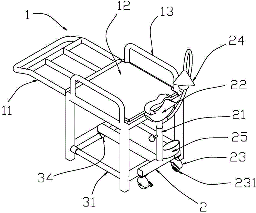
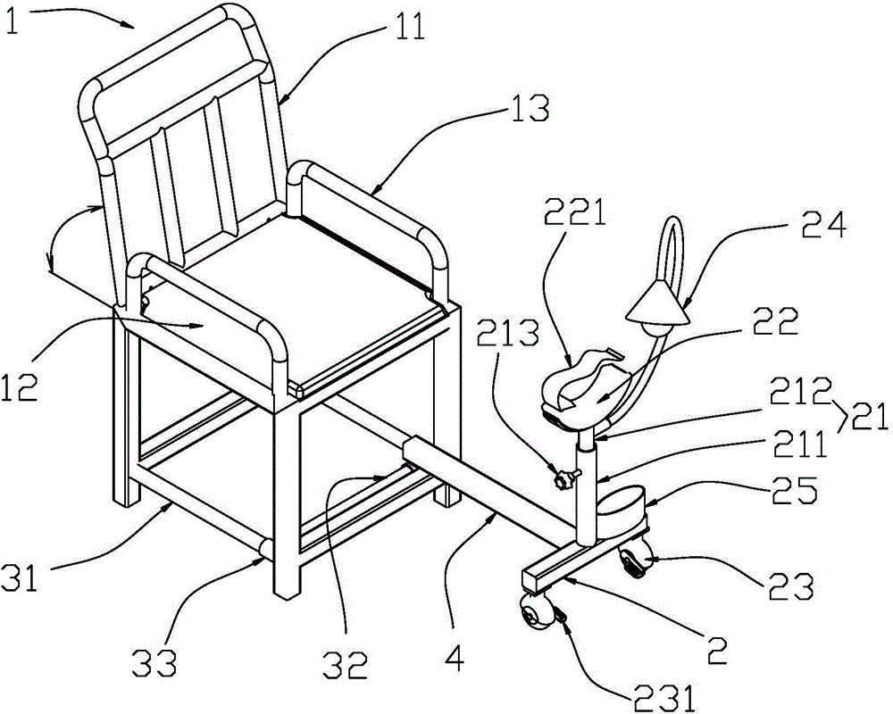
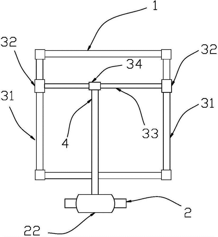
[0034] Embodiment two: combine figure 2 , Figure 4 , the two-axis motion system includes a slider 51 and vertically arranged front and rear guide rods 52, left and right guide rods 53, the slider 51 is provided with mutually perpendicular through holes, the front and rear guide rods 52, left and right guide rods The rods 53 respectively pass through a through hole. The left and right guide rods 53 are fixed below the seat plate 12 , and the front ends of the front and rear guide rods 52 are connected with the bracket 2 . When the front and rear guide rods 52 move, they drive the support 2 to move back and forth, and when the slider 51 moves, they drive the front and rear guide rods 52 and the support 2 to move left and right together.

Embodiment 3

[0035] Example Three: Combining figure 2 , Figure 5, the two-axis motion system includes a left and right guide rod 61 and a telescopic rod 62, and the telescopic rod 62 includes a matching inner sleeve 621 and an outer sleeve 622, and the left and right guide rods 61 are fixed under the seat plate 12, The left and right guide rods 61 are provided with sliders 63 , and the bracket 2 and the sliders 63 are respectively connected to the outer casing 622 and the inner casing 621 of the telescopic rod 62 . When the inner casing 621 and the outer casing 622 move relative to each other, the bracket 2 is driven to move back and forth, and the slider 63 drives the bracket 2 and the telescopic rod 62 to move left and right when moving on the left and right guide rods 61 .

[0036] In actual use, the present invention adopts the two-axis motion system in Embodiment 1.

[0037] combine Figure 1-Figure 3 , the method of use of the present invention is:

[0038] 1) Let the patient s...


PUM


Abstract

The invention provides a diabetic foot nursing chair. The diabetic foot nursing chair comprises a chair, wherein the chair is provided with a chair back and a seat board. The diabetic foot nursing chair further comprises a bracket which is located in front of the chair, wherein a lifting structure which is arranged vertically is arranged on the bracket; a foot pad is arranged at the upper end of the lifting structure; a two-axis movement system which is arranged in the horizontal direction is mounted below the seat board of the chair, and the bracket is connected with the two-axis movement system so as to realize left-and-right movement and back-and-forth movement; the lifting structure comprises a sleeve and a lifting rod; the sleeve is fixedly arranged on the bracket; the lifting rod is mounted in the sleeve; the sleeve and the lifting rod are located through a locating pin, and the foot pad is mounted at the top end of the lifting rod. According to the diabetic foot nursing chair, the bracket is adjustable in height, the foot pad can be rotationally located, and meanwhile, accessory equipment, such as a binding band, is further equipped, so that during use, the requirements of users on comfort degree can be met, convenience can also be brought for actual operation of medical personnel, and professional nursing operation can achieve the best implementation effect.

Description

technical field [0001] The invention relates to a diabetic foot nursing chair. Background technique [0002] With the increase of age and the prolongation of illness time in diabetic patients, the incidence of neuropathy and vascular disease will increase. Patients have irregular growth of toenails, such as ingrown nails, thickened nails, hook nails, etc. The above-mentioned factors bring pain and discomfort to the patient, and produce compression on the tissue adjacent to the lesion, resulting in local ischemia, hypoxia and ulceration. Timely professional trimming of stubborn corpus callosum and abnormal toenails is crucial to prevent the occurrence and development of foot ulcers. In order to perform the above-mentioned specialized nursing operations, the patient needs to be placed in a comfortable position and the foot needs to be fixed securely, and the medical staff who perform the technical operation need to be provided with an easy-to-operate view angle and force-app...

Claims


Application Information

Patent Timeline
Patent Type & Authority Applications(China)
IPC IPC(8): A61F5/00
Inventor 白姣姣孙皎纪丽臧娴卢湘
Owner HUADONG HOSPITAL
Learn More