Elevator Controls
A technology for control devices and elevators, applied in the field of elevator control devices
- Summary
- Abstract
- Description
- Claims
- Application Information
AI Technical Summary
Problems solved by technology
Method used
Image

Examples
no. 1 Embodiment approach
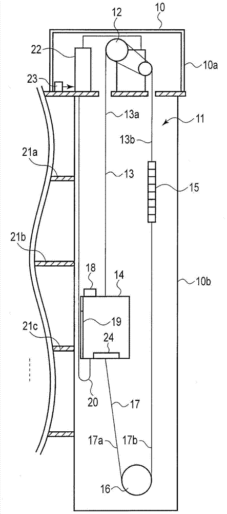
[0038] figure 1 It is a figure which shows the structure of the elevator of 1st Embodiment. Now, assume a case where one elevator 11 is installed in a certain building 10 . In addition, in the present embodiment, the elevator 11 is used as an observation elevator, and runs back and forth between the lobby floor on the lower floor of the building 10 and the observation floor on the upper floor.
[0039] Such as figure 1 As shown, a hoist 12 as a driving source of an elevator 11 is installed in a machine room 10 a at the uppermost part of a building 10 . Moreover, in the machine-room-less elevator, the hoisting machine 12 is installed in the upper part in the hoistway 10b.
[0040] A main rope 13 is wound around the hoist 12 . A passenger car 14 is attached to one end side of the main rope 13 . A counterweight 15 is attached to the other end side of the main rope 13 .
[0041] A compensating sheave (compensating sheave) 16 is provided at the lowermost portion of the lift p...
no. 2 Embodiment approach
[0098] Next, a second embodiment will be described.
[0099] Such as Figure 8 As shown, the first floor of the lower floor of the building 10 is the lobby floor, the 20th floor of the upper floor is the observation floor, and each is a resonance floor. Here, it is assumed that non-resonant floors exist in the vicinity of the lobby floor and the observation floor. exist Figure 8 In the example, layers 6 and 15 are non-resonant layers.
[0100] The "non-resonant floor" refers to a floor with little rope vibration accompanying the shaking of the building 10 . For example, the main ropes 13a on the side of the car 14 have a characteristic of swinging at the maximum when the car 14 is in the vicinity of the lowest floor. Therefore, about the main rope 13a, the vicinity of the lowest layer becomes a resonant layer. The main rope 13b on the side of the counterweight 15 has a characteristic of swinging at a maximum amplitude when the passenger car 14 is near the uppermost floor...
no. 3 Embodiment approach
[0125] Next, a third embodiment will be described.
[0126] In the above-mentioned first and second embodiments, the description has been made on the assumption that passengers board and descend on the same floor. In the third embodiment, a case where boarding and descending of passengers are performed on different floors is assumed.
[0127] Figure 15 It is a figure which shows an example of the observation elevator of 3rd Embodiment. According to the specifications of the building 10, it is divided into a floor for passengers to board and a floor for passengers to go down. In this example, the 1st floor of the lower floor of the building 10 is a floor dedicated to elevators (lobby floor), the 2nd floor is a floor dedicated to elevators, the 20th floor of the upper floor is a floor dedicated to elevators (view floor), and the 19th floor is a floor dedicated to elevators. Dedicated floor for elevators.
[0128] Such as Figure 16 As shown, the passenger car 14 repeats th...
PUM
 Abstract
Description
Claims
Application Information
 - R&D
- Intellectual Property
- Life Sciences
- Materials
- Tech Scout
- Unparalleled Data Quality
- Higher Quality Content
- 60% Fewer Hallucinations
Browse by: Latest US Patents, China's latest patents, Technical Efficacy Thesaurus, Application Domain, Technology Topic, Popular Technical Reports.
© 2025 PatSnap. All rights reserved.Legal|Privacy policy|Modern Slavery Act Transparency Statement|Sitemap|About US| Contact US: help@patsnap.com