
Multi-function injector drive controller

A technology for driving controllers and injectors, applied in engine control, fuel injection control, electrical control, etc., can solve problems such as difficult control of precision, many external circuit devices, and high requirements for boost modules, and solve the problem of fuel injection overlap. , easy to control equipment, solve the effect of taking up more resources

Active Publication Date: 2018-01-12
意昂神州(北京)科技有限公司
View PDF4 Cites 0 Cited by
  • Summary
  • Abstract
  • Description
  • Claims
  • Application Information

AI Technical Summary

Problems solved by technology

[0005] Divided from the different ways of driving signal synthesis, there are mainly two forms: one is to use the main controller to control the output, and use the timing interrupt of the controller to realize the control pulses in each stage of the driving signal; this method It needs to occupy a lot of interrupt resources, which is not good for the operation of the controller, that is, the complex interrupt response will slow down the running speed of the controller, and the increase in the number of interrupts will lead to potential program problems; therefore, the control accuracy of this method hard to guarantee
Another way is to use analog circuits to build splicing and combination. It needs to use the sampling feedback circuit for continuous feedback control. At the same time, it needs to use pulse generators, triggers, comparators, operational amplifiers, transistors, etc. to build different stages of Control signals, so as to achieve the realization of different current requirements; this method reduces the resource occupation of the main controller, but there are many external circuit devices and complicated, involving high-frequency digital circuits and sensitive analog c

Method used


Image

  • Multi-function injector drive controller
  • Multi-function injector drive controller
  • Multi-function injector drive controller

Examples


Example Embodiment

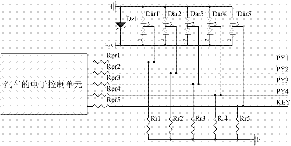
[0033] See Figure 1 ~ Figure 7 In the figure, the multi-function fuel injector drive controller contains interface protection module, main control module, pre-drive module, drive module, boost module and power management module, and the fuel injection output from the electronic control unit ECU (Electronic Control Unit) of the automobile The control signal is input to the main control module after passing through the interface protection module, the drive signal output by the main control module enters the drive module after the pre-drive module, the drive module controls the operation of the injector, and the injector current detection signal output by the drive module is pre-driven After the module is fed back to the main control module, the boost module provides high voltage for the pre-drive module and the drive module, and the power management module provides power for the interface protection module, the main control module, the pre-drive module, the drive module and the ...


PUM


Abstract

The invention relates to a multifunctional fuel injector drive controller, which includes an interface protection module, a main control module, a pre-drive module, a drive module, a boost module and a power management module, and the fuel injection control signal output by the electronic control unit of the automobile After passing through the interface protection module, it is input to the main control module. The drive signal output by the main control module enters the drive module after passing through the pre-drive module. Feedback to the main control module, the boost module provides high voltage for the pre-drive module and the drive module, and the power management module supplies power for the interface protection module, the main control module, the pre-drive module, the drive module and the boost module; the invention provides a Efficient, accurate and reliable multi-functional fuel injector drive controller.

Description

technical field [0001] The invention relates to a fuel injector driving controller, in particular to a multifunctional fuel injector driving controller. Background technique [0002] At present, with the continuous application and promotion of high-pressure common rail diesel engines and in-cylinder direct injection gasoline engines, people have higher and higher requirements for the characteristics of fuel injectors, especially for the dynamic response speed of fuel injector opening and closing. The higher the engine controller is, the higher it is, which requires the engine controller to have a high-performance drive circuit and an efficient control strategy. At the same time, it is also necessary to ensure that the engine can run safely and reliably in harsh environments, which poses a great challenge to the development and design of the engine controller. challenge. Existing engine controllers are only signal-level control units, or have low-power drive resources (some ...

Claims


Application Information

Patent Timeline
IPC IPC(8): F02M51/06F02D41/38
Inventor 史国军路斌
Owner 意昂神州(北京)科技有限公司
Learn More