Pipe fitting structure

A pipe fitting and connecting pipe technology, applied in the field of combined pipe fittings, can solve problems such as inconvenient rotation, inconvenient use, and complex structure, and achieve the effects of easy assembly and fixing, reduced production costs, and improved user experience

Inactive Publication Date: 2015-07-29
GRAND IPEARL ELECTRONICS & TECH
View PDF9 Cites 3 Cited by
  • Summary
  • Abstract
  • Description
  • Claims
  • Application Information

AI Technical Summary

Problems solved by technology

[0002] At present, in order to facilitate installation and storage, two pipes are usually nested with each other. One way is to put a pipe with a large diameter on a pipe with a small diameter, and then clamp it with a locking device to achieve expansion and fixation. However, this structure is not conducive to timely expansi

Method used


Image

  • Pipe fitting structure
  • Pipe fitting structure
  • Pipe fitting structure

Examples


Embodiment Construction

[0036] Embodiments of the present invention are described in detail below in conjunction with accompanying drawings:

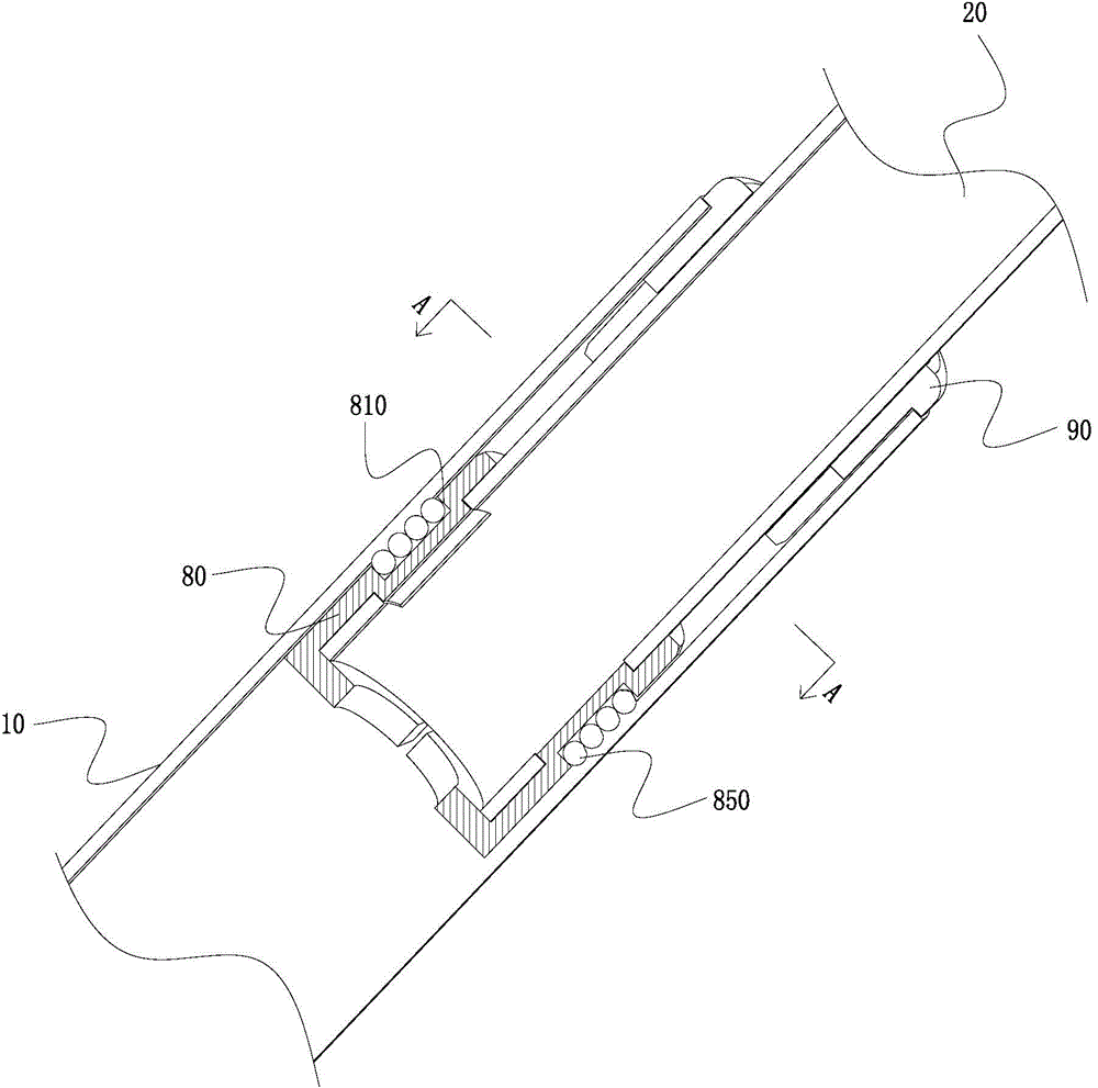
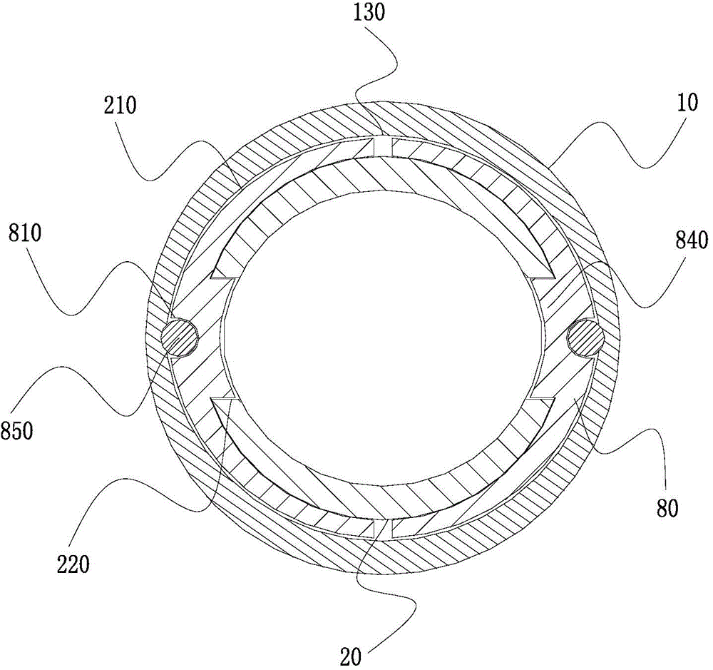
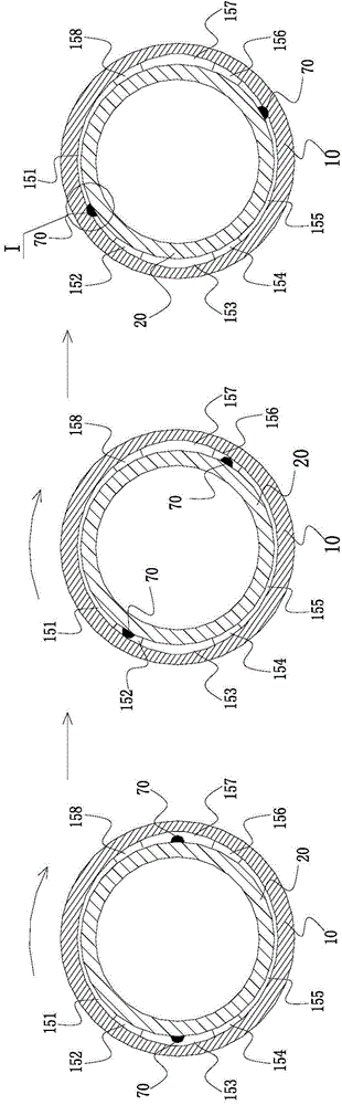
[0037] like Figure 1 to Figure 5As shown, the pipe fitting structure at least includes a first connecting pipe 10 and a second connecting pipe 20 sleeved in the first connecting pipe. The first connecting pipe 10 is provided with a first mating surface 130, and the second connecting pipe 20 is provided with a The second mating portion 210 opposite to the first mating surface 130, the first mating surface 130 is sequentially formed with at least a first interference fit area 151, a first transition fit area 152, a first clearance fit area 153, and a second transition fit area along the circumferential direction. The fit zone 154, the second interference fit zone 155, the third transition fit zone 156, the second clearance fit zone 157 and the fourth transition fit zone 158, the two convex parts 70 on the second fit part 210 and the second A mating surface 130...


PUM


Abstract

The invention relates to a pipe fitting structure. The pipe fitting structure comprises at least one first connecting pipe, and a second connecting pipe which is sleeved with the first connecting pipe; the first connecting pipe is provided with a first matching surface; a second fitting part opposite to the first fitting surface is arranged on the second connecting tube; at least one first interference fit area, a first transition fitting area, a first gap fitting area, a second transition fitting area, a second interference fit area, a third transition fitting area, a second gap fitting area and a fourth transition fitting area are sequentially circumferentially formed on the first fitting surface; at least one extrusion part and a second extrusion part which are in match with the first fitting surface are formed on two top point parts with the largest distance on the second fitting part; the second extrusion part is positioned in the first interference fit area; the second extrusion part is positioned in the second interference fit area. The pipe fitting structure can be clamped by two-way rotating, so that the assembling and fixing are convenient; the structure is simple; a locking buckle device is saved, so that the production cost is reduced.

Description

technical field [0001] The invention relates to a combined pipe fitting, in particular to a pipe fitting structure. Background technique [0002] At present, in order to facilitate installation and storage, two pipes are usually nested with each other. One way is to put a pipe with a large diameter on a pipe with a small diameter, and then clamp it with a locking device to achieve expansion and fixation. However, this structure is not conducive to timely expansion and fixation, the structure is too complicated and inconvenient to use, and the production cost is high; and the other method is to clamp through the diameter difference of two special-shaped tubes, but the product assembled by special-shaped tubes, It is not easy to rotate, which affects the user experience of the product. Contents of the invention [0003] The object of the present invention is to provide a pipe fitting structure, which can be clamped by two-way rotation, is easy to assemble and fix, has a sim...

Claims


Application Information

Patent Timeline
IPC IPC(8): F16B7/10
CPCF16B7/10
Inventor 王鸿
Owner GRAND IPEARL ELECTRONICS & TECH
Why Eureka
Try Eureka