One-way clutch and crank-type continuously-variable transmission

A one-way clutch, axial technology, applied in one-way clutches, clutches, belts/chains/gears, etc., can solve problems that hinder the smooth engagement of one-way clutches, wear, etc., and achieve the effect of improving engagement responsiveness

Active Publication Date: 2015-07-29
HONDA MOTOR CO LTD
View PDF6 Cites 1 Cited by
  • Summary
  • Abstract
  • Description
  • Claims
  • Application Information

AI Technical Summary

Problems solved by technology

[0005] However, even if an axial spring is provided to prevent the rollers from tilting, if the rollers tilt slightly while moving from the damping point to the reference point, the outer peripheral portion of the second end surface of the rollers will be hooked on the cage. On the side, there is a possibility that the rollers are inclined at the reference point to prevent the smooth engagement of the one-way clutch, or the outer peripheral part of the second end surface of the rollers and the side surface of the cage rub against each other and become a cause of wear

Method used


Image

  • One-way clutch and crank-type continuously-variable transmission
  • One-way clutch and crank-type continuously-variable transmission
  • One-way clutch and crank-type continuously-variable transmission

Examples


Embodiment Construction

[0031] Below, according to Figure 1 to Figure 12 Embodiments of the present invention will be described.

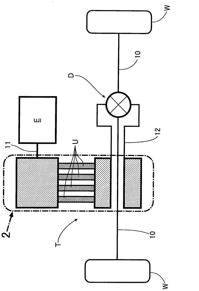
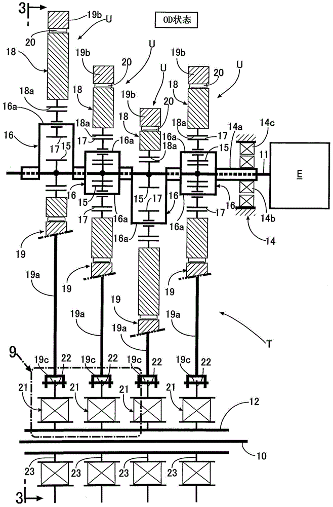
[0032] like Figure 1 ~ Figure 3 As shown, the vehicle power transmission device that transmits the driving force of the engine E to the driving wheels W, W via the left and right axles 10 , 10 includes a crank-type continuously variable transmission T and a differential gear D. As shown in FIG. The continuously variable transmission T of this embodiment is obtained by superimposing a plurality of (four in the embodiment) power transmission units U having the same structure in the axial direction, and these power transmission units U have a common input arranged in parallel. The shaft 11 and the output shaft 12 are common, and the rotation of the input shaft 11 is decelerated or accelerated to be transmitted to the output shaft 12 .

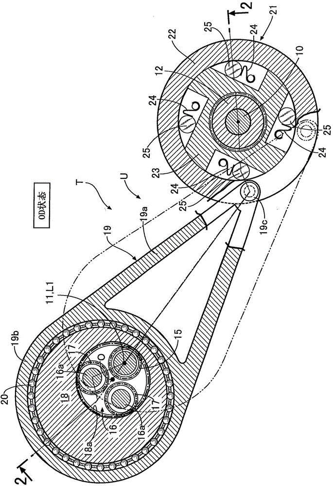
[0033] Below, according to Figure 2 ~ Figure 6 The structure of the continuously variable transmission T will be described.

[0034]F...


PUM


Abstract

The invention provides a one-way clutch and a crank-type continuously-variable transmission. A peripheral part of an end face of a roller applying a force in an axial direction through an axial spring is preventing from being engaged with a side surface of a maintaining frame. Because a frictional force acting on a first end face (25a) of the roller (25) is consistent with a frictional force acting on a second end face (25b) of the roller (25), thereby preventing the roller (25) from being inclined because of the imbalance between the frictional forces of the first and second end faces (25a, 25b) during the movement from a reference point and an engagement point, preventing the inclined roller (25) from being worn caused by the contact of the first and second end faces (25a, 25b) of the roller (25) with a first side surface (36a) and a second side surface (36b) of an inner ring (36). Moreover, the roller (25) can be enabled to be smoothly engaged between an outer peripheral surface of an internal part (23) and an inner peripheral surface (22a) of an external part (22), thereby improving the joint responsiveness of the one-way clutch (21).

Description

technical field [0001] The present invention relates to a one-way clutch in which a plurality of rollers held on a cage are urged in a circumferential direction using an engaging spring, and a crank type continuously variable transmission having the same. The cage is disposed between the outer peripheral surface of the inner member and the inner peripheral surface of the outer member, and the rollers are engaged with the outer peripheral surface and the inner peripheral surface of the outer member by relative rotation of the inner member and the outer member in one direction. The driving force is transmitted between the inner peripheral surfaces. Background technique [0002] According to the following patent document 1, it is known to use a coil spring to form an engaging spring that biases the rollers of the one-way clutch in the circumferential direction, and to provide a mechanism for restricting the axial displacement of the coil spring at the cage holding the rollers. ...

Claims


Application Information

Patent Timeline
Patent Type & Authority Applications(China)
IPC IPC(8): F16D41/064F16H37/12
Inventor 大图达也
Owner HONDA MOTOR CO LTD
Why Eureka
Try Eureka