one-way clutch
A one-way clutch, axial technology, applied in the direction of one-way clutches, clutches, mechanical equipment, etc., can solve the problems that hinder the smooth engagement and wear of one-way clutches, reduce friction, reduce contact area, and prevent tilting Effect
- Summary
- Abstract
- Description
- Claims
- Application Information
AI Technical Summary
Problems solved by technology
Method used
Image
Examples
no. 1 Embodiment approach
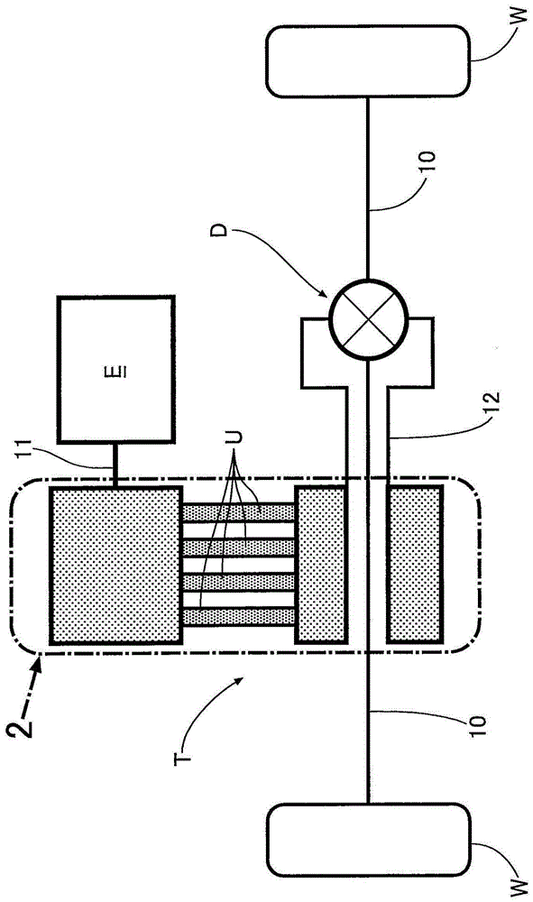
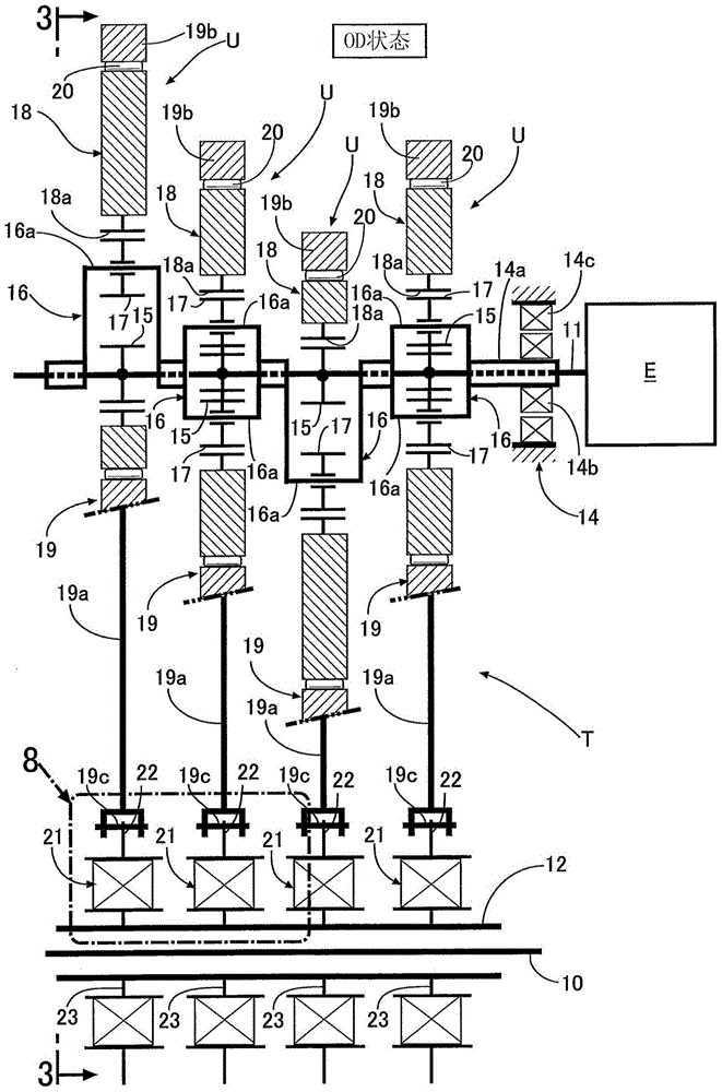
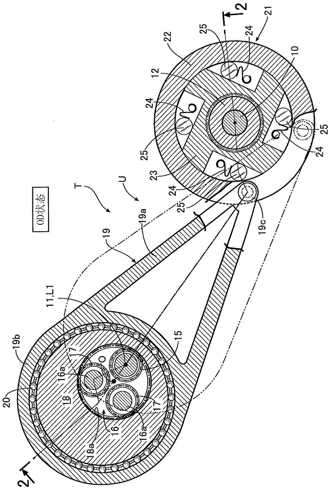
[0043] Below, according to Figure 1 to Figure 11 , the first embodiment of the present invention will be described.
[0044] Such as Figure 1 ~ Figure 3As shown, the vehicle power transmission device that transmits the driving force of the engine E to the drive wheels W, W via left and right axles 10 , 10 includes a crank-type continuously variable transmission T and a differential D. The continuously variable transmission T of this embodiment is obtained by stacking a plurality of (four in the embodiment) power transmission units U having the same structure in the axial direction, and these power transmission units U have a common input that is arranged in parallel. The shaft 11 and the common output shaft 12, the rotation of the input shaft 11 is transmitted to the output shaft 12 after being decelerated or accelerated.
[0045] Next, based on Figure 2 ~ Figure 6 , the structure of the continuously variable transmission T will be described.
[0046] First, the configu...
no. 2 Embodiment approach
[0077] Next, according to Figure 12 with Figure 13 , and the second embodiment of the present invention will be described.
[0078] In the first embodiment, the convex portion 36c protruding from the second side surface 36b has a circular shape, whereas in the second embodiment, the convex portion 36c protruding from the second side surface 36b has an annular shape. The outer diameter D1 of the annular convex portion 36c is the same as that of the first embodiment. Furthermore, an oil supply passage 36d formed inside the inner member 23 opens at the center of the annular convex portion 36c, and oil from an oil pump (not shown) is supplied to the center of the convex portion 36c via the oil supply passage 36d.
[0079] According to the present embodiment, the contact area with the second end surface 25b of the roller 25 is reduced by forming the convex portion 36c in an annular shape. The difference in friction acting between the axial spring 38 and the first end surface 2...
no. 3 Embodiment approach
[0082] Next, according to Figure 14 , the third embodiment of the present invention will be described.
[0083] The third embodiment is an improvement of the above-mentioned first embodiment. The convex portion 36c of the first embodiment is circular. In contrast, the convex portion 36c of the third embodiment has a long diameter along the moving direction of the roller 25 (that is, the outside Circumferential direction of piece 23) oval shape. The major diameter D2 of the ellipse is the same as the diameter D1 of the circular convex portion 36c in the first embodiment, and the minor diameter D3 of the ellipse is smaller than the diameter D1.
[0084] According to the present embodiment, the convex portion 36c of the second side surface 36b is an elliptical shape whose long diameter is along the moving direction of the roller 25, therefore, it is similar to the circular convex portion 36c having the same diameter D1 as the long diameter D2 (refer to the first Compared with ...
PUM
 Abstract
Description
Claims
Application Information
 - R&D
- Intellectual Property
- Life Sciences
- Materials
- Tech Scout
- Unparalleled Data Quality
- Higher Quality Content
- 60% Fewer Hallucinations
Browse by: Latest US Patents, China's latest patents, Technical Efficacy Thesaurus, Application Domain, Technology Topic, Popular Technical Reports.
© 2025 PatSnap. All rights reserved.Legal|Privacy policy|Modern Slavery Act Transparency Statement|Sitemap|About US| Contact US: help@patsnap.com


