Lens barrel

A lens and lens barrel technology, applied in the direction of instruments, installation, optics, etc., can solve the problems of not considering the advance and retreat of moving frame parts, not much consideration of abnormal sound, noise, etc., to achieve noise realization, suppression of abnormal sound, and high-precision action Effect

Active Publication Date: 2015-07-29
OM DIGITAL SOLUTIONS CORP
View PDF4 Cites 2 Cited by
  • Summary
  • Abstract
  • Description
  • Claims
  • Application Information

AI Technical Summary

Problems solved by technology

[0007] However, in the conventional lens barrels disclosed in the above-mentioned Japanese Patent Application Laid-Open No. 9-145976, etc., for example, the possibility that vibration or the like caused by an electric drive source (motor) or the like may hinder the forward and backward movement of the movable frame member is not considered.
In addition, in the past, the abnormal sound, noise, etc. caused by vibration, etc. were not considered much.

Method used


Image

  • Lens barrel
  • Lens barrel
  • Lens barrel

Examples


Embodiment Construction

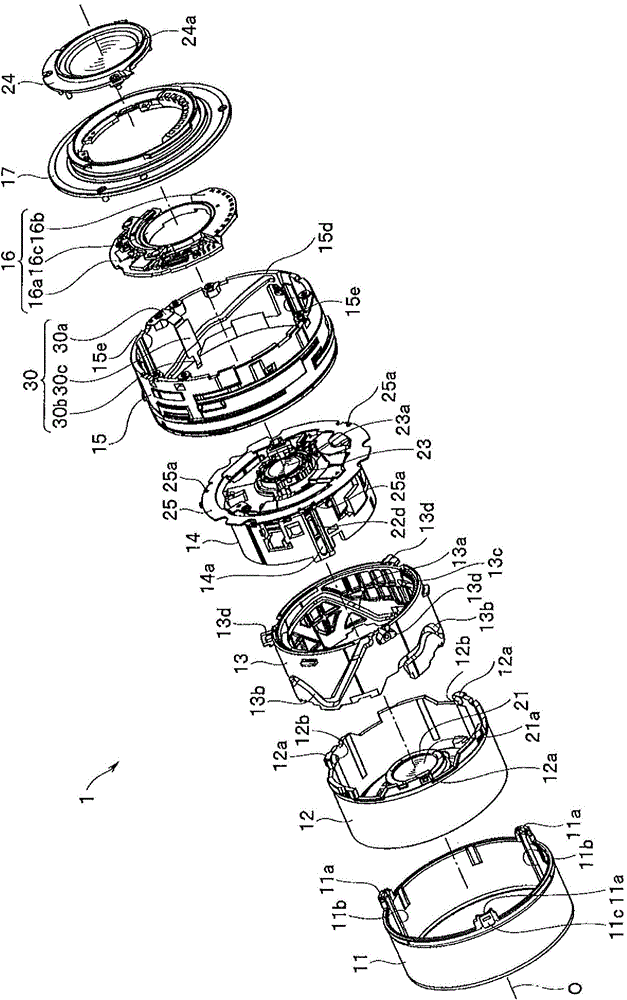
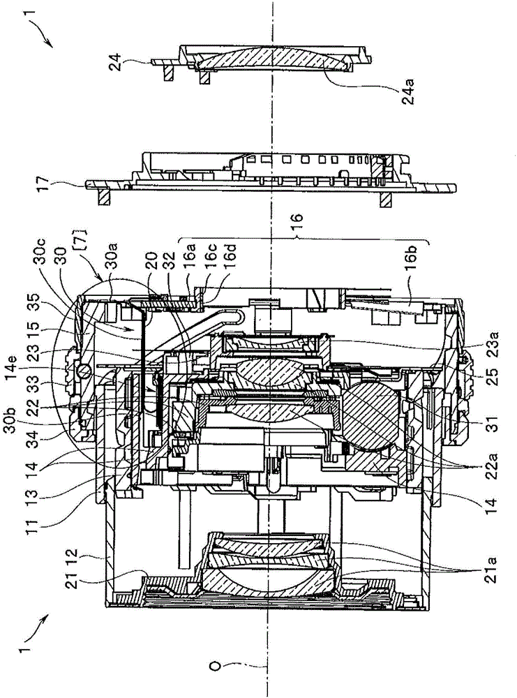
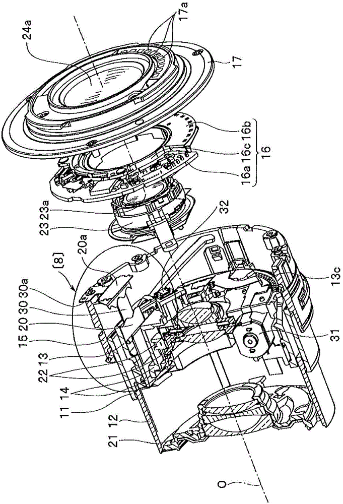
[0021] Hereinafter, the present invention will be described with reference to the illustrated embodiments. One embodiment of the present invention illustrates, for example, a lens barrel applied to an imaging device such as a digital camera or a video camera (hereinafter simply referred to as a camera). It is an imaging optical system that forms a subject image, and can move a part of the optical lens groups among the plurality of optical lens groups constituting the imaging optical system in a direction along the optical axis.

[0022] In addition, in the present embodiment, the optical axis of the photographing optical system in the lens barrel is denoted by a symbol O. In the direction along the optical axis O, the side where the subject is located opposite to the front surface of the camera (not shown) equipped with the lens barrel is referred to as the front. The side where the head is located is called the rear.

[0023] In addition, in each drawing used in the followi...


PUM


Abstract

The present invention provides a lens barrel, which can mitigate the vibration generated by an electric drive source (such as a motor or the like) to realize the silence. The lens barrel comprises an electric drive source (31, 32); a first frame (15) served as one of multiple frame parts of the lens barrel (1), a second frame (14) provided with the electric drive source and moving relative to the first frame; a flexible printed substrate arranged between the electric drive source and the first frame to electrically connect the electric drive source with the first frame; and a guide plate (30) provided with a fixed part (30a) and a crimping part (30b) and shaped in a beam shape to be elastic. The lens barrel is internally provided with the flexible printed substrate. One of the first frame and the second frame is fixedly provided with the fixed part, so as to enable the crimping part to abut against the second frame or the first frame.

Description

technical field [0001] The present invention relates to a lens barrel, which is composed of a plurality of frame members, has an electric driving source and a flexible printed board connected to the electric driving source, and is configured such that a part of the plurality of frame members moves along the optical axis. direction in which to advance and retreat freely. Background technique [0002] Conventionally, in a lens barrel used in an imaging device or the like, a focusing operation (focusing) and a zooming operation ( zoom). In this case, as a driving source for moving the frame member forward and backward, for example, an electric driving source such as an electric motor is generally used and put into practical use. [0003] In such a lens barrel, for example, as an electric substrate etc. which are fixedly arranged on a fixed frame member in a fixed state among a plurality of frame members, and a movable frame which is arranged to move forward and backward in th...

Claims


Application Information

Patent Timeline
Patent Type & Authority Applications(China)
IPC IPC(8): G02B7/00
CPCG02B7/00
Inventor 阴山直启西川千裕石塚和宜
Owner OM DIGITAL SOLUTIONS CORP
Why Eureka
Try Eureka