Soot blower

A technology of soot blowing device and soot blowing pipe is applied in the treatment of combustion products, combustion method, and removal of solid residue, etc., which can solve the problem that the steam soot blowing device is not suitable for large-scale boiler blowing and so on.

Inactive Publication Date: 2015-08-05
广西梧锅锅炉制造有限公司
View PDF8 Cites 0 Cited by
  • Summary
  • Abstract
  • Description
  • Claims
  • Application Information

AI Technical Summary

Problems solved by technology

[0003] The problem to be solved by the present invention is to provide a soot blowing device to solve the problem that the existing steam soot blowing device is not suitable for spraying and sweeping large boilers

Method used


Image

  • Soot blower
  • Soot blower
  • Soot blower

Examples


Embodiment Construction

[0012] Embodiments of the present invention are described in further detail below in conjunction with the accompanying drawings:

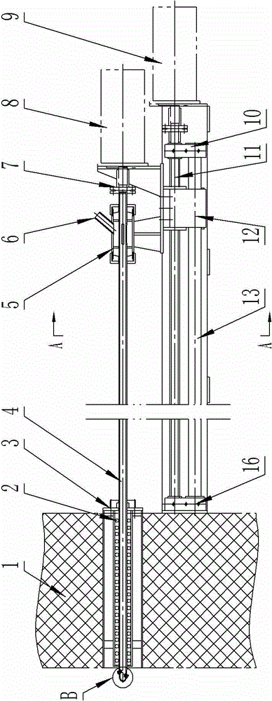
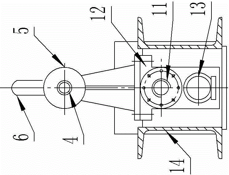
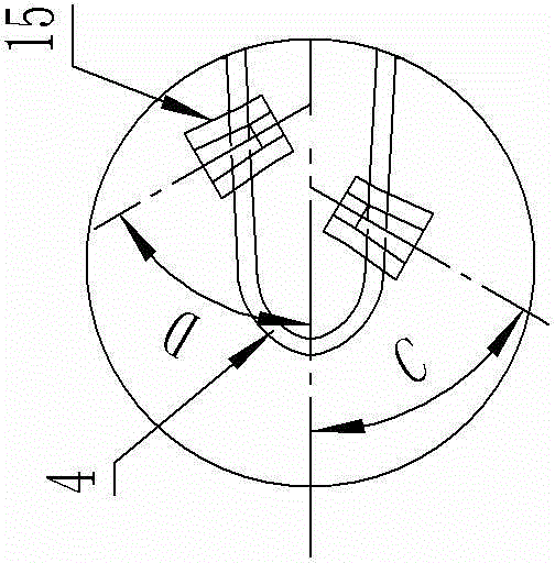
[0013] like figure 1 , figure 2 , image 3 The soot blowing device shown includes an air chamber 5 with an air inlet pipe 6, the air chamber 5 is provided with a soot blowing pipe 4, the opening of the soot blowing pipe 4 is in the air chamber 4, and the nozzle 15 of the soot blowing pipe 4 Out of the air chamber 5, the soot blowing pipe 4 is connected to the power machine 8 through the coupling 7 at the other end of the air chamber 5, where the power machine 8 is a reducer. The soot blowing pipe 4 extends into the hole of the furnace wall 1 with the asbestos rope 2, and then obliquely protrudes two nozzles 15. The two nozzles 15 are symmetrically arranged on the axial centerline of the soot blowing pipe 4. The inclination angles C and D is different, and the inclination angle is selected within the range of 35° to 55°. Through the rotation of ...


PUM


Abstract

The invention discloses a soot blower. The soot blower comprises an air chamber with an air inlet pipe, wherein a soot blow pipe is arranged in the air chamber; spray heads of the soot blow pipe extend out of the air chamber; the soot blow pipe is connected with a power machine at the other end of the air chamber through a coupling; the soot blow pipe extends into a pore passage with an asbestos rope on a furnace wall and then slantwise extends out of two spray heads; a supporting guide rail is arranged just below the air chamber and the soot blow pipe; one end of the supporting guide rail is arranged on the furnace wall, and the other end of the supporting guide rail is provided with a supporting seat; the supporting guide rail comprises a lead screw and a guide rod on the lower side of the lead screw; the lead screw is connected with a drive motor; the lead screw and the guide rod are provided with a lead screw seat; the air chamber and the power machine are fixedly arranged on the lead screw seat. According to the soot blower, the problem that the existing steam soot blow device is not suitable for spray blowing of large-sized boilers can be solved.

Description

technical field [0001] The invention relates to the technical field of boiler tools, in particular to a steam soot blowing device for large boiler soot blowing. Background technique [0002] The existing steam soot blowing device for boiler soot blowing generally includes an air chamber with an air inlet pipe, and a soot blowing pipe is arranged in the air chamber. The other end of the tube in the air chamber is connected to the power machine through a coupling. During soot blowing, the power machine drives the soot blowing pipe to rotate to make the pressure of the blown gas more uniform. The ash pipe can be extended into the depth of the boiler for spraying; in addition, the trumpet-shaped nozzle is also likely to cause a dead angle of spraying, and the spraying effect is poor. Therefore, it is necessary to design a highly efficient and reliable large-scale boiler soot blowing device to be suitable for the spraying of large-scale boilers. Contents of the invention [...

Claims


Application Information

Patent Timeline
Patent Type & Authority Applications(China)
IPC IPC(8): F23J3/00
Inventor 叶洪武梁海冼剑明
Owner 广西梧锅锅炉制造有限公司
Why Eureka
Try Eureka