
Downhole pulse generating device for through-bore operations

A technology for downhole tools and longitudinal holes, which is applied to vibration generating devices, driving devices for drilling in boreholes, and vibration drilling, etc., which can solve the problem of difficult removal of pulse generating devices, pulse generating devices that do not allow capture or drilling operations And other issues

Active Publication Date: 2015-08-05
NAT OILWELL VARCO LP
View PDF7 Cites 6 Cited by
  • Summary
  • Abstract
  • Description
  • Claims
  • Application Information

AI Technical Summary

Problems solved by technology

[0003] Conventional pulse generators do not allow trapping or perforation under the device
Additionally, it is difficult to remove the pulse generator from the wellbore without removing a major portion of the drill string

Method used


Image

  • Downhole pulse generating device for through-bore operations
  • Downhole pulse generating device for through-bore operations
  • Downhole pulse generating device for through-bore operations

Examples


Embodiment Construction

[0016] It should be understood that the ensuing disclosure describes several exemplary embodiments for implementing various features, structures or functions of the invention. Exemplary embodiments of components, arrangements, and configurations are described below to simplify the present invention; however, these exemplary embodiments are provided more as examples only and are not intended to limit the scope of the present invention. Furthermore, this disclosure may reuse reference numerals and / or letters in different exemplary embodiments and throughout the drawings provided herein. This repetition is for the purpose of simplicity and clarity and is not intended in any way to point out a relationship between the different exemplary embodiments and / or configurations set forth in the different figures. Furthermore, in the ensuing description, a first feature formed on or over a second feature may include embodiments wherein the first and second features are formed in direct co...


PUM


Abstract

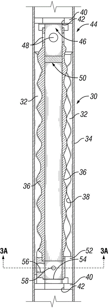
A downhole tool comprises a housing having a longitudinal bore and an agitator assembly disposed within the longitudinal bore of the housing. A removable component is disposed within the longitudinal bore and can be removed from the housing so as to at least partially open the longitudinal bore.

Description

technical field [0001] The present invention generally relates to a method and apparatus for generating vibration or fluid pulses with a downhole tool. Still further, the present invention relates to a method and apparatus that allow retrieving components of a downhole pulse generating device from a drill string or otherwise assist in capture and perforation activities. Background technique [0002] Downhole pulse generators are used to generate fluctuations in fluid pressure, which create vibrations in the drill string. This vibration or pulsation can help avoid build-up of solid material around the drill string, which can reduce friction and prevent the drill string from sticking in the well. Therefore, the application of the pulse generator can help to extend the operating range of the drill tool assembly. [0003] Conventional pulse generating devices do not allow trapping or perforating operations to be performed under the device. Furthermore, it is difficult to remo...

Claims


Application Information

Patent Timeline
Patent Type & Authority Applications(China)
IPC IPC(8): E21B4/02F03B13/02
CPCE21B31/005E21B28/00E21B7/24
Inventor 罗素·吉尔伦哈什·甘亚姆小詹姆斯 R.·斯特里特迪普提·丝特勒艾伦 H.·基奇希兰·瓦阿斯默里·吉尔伯特森
Owner NAT OILWELL VARCO LP
Features
  • Generate Ideas
  • Intellectual Property
  • Life Sciences
  • Materials
  • Tech Scout
  • Unparalleled Data Quality
  • Higher Quality Content
  • 60% Fewer Hallucinations
Learn More