
Pneumatic tire

A technology for pneumatic tires and treads, applied in tire parts, treads, transportation and packaging, etc., to improve durability, suppress the impact of quality and production costs, and suppress dumping

Active Publication Date: 2015-08-12
SUMITOMO RUBBER IND LTD
View PDF7 Cites 1 Cited by
  • Summary
  • Abstract
  • Description
  • Claims
  • Application Information

AI Technical Summary

Problems solved by technology

High rigidity suppresses deformation

Method used


Image

  • Pneumatic tire
  • Pneumatic tire
  • Pneumatic tire

Examples


Embodiment 1

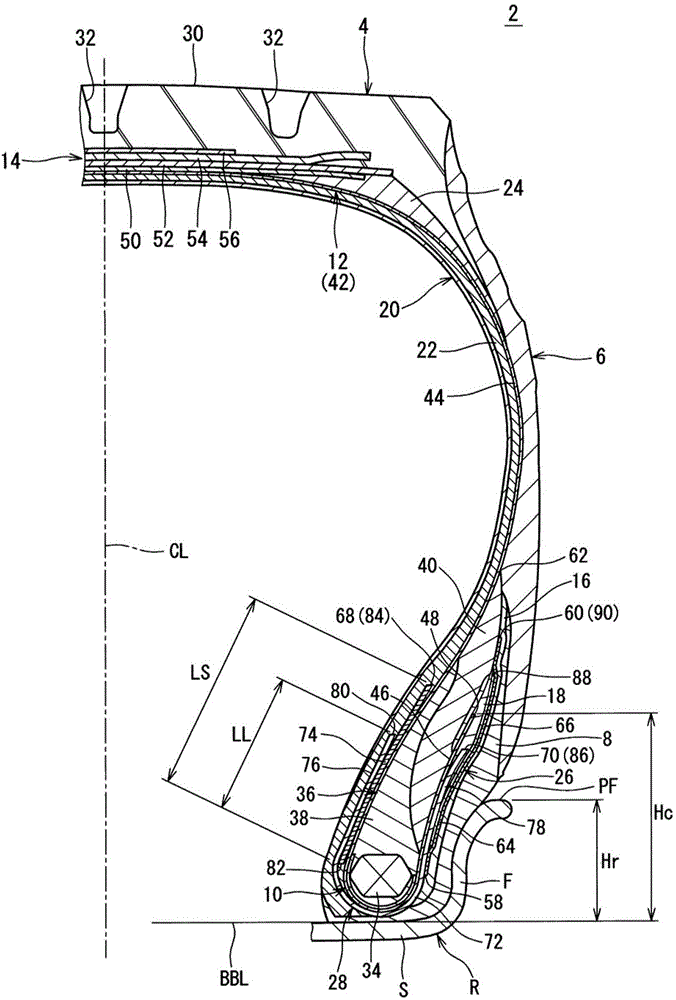
[0099] Obtained the possession of embodiment 1 figure 1 The basic structure shown is a heavy-duty pneumatic tire having the specifications shown in Table 1 below. The tire size is 12.00R20. Therefore, the size of the rim on which this tire is assembled is 8.8×20, and the height Hr of the flange of the rim is 45 mm.

[0100] The carcass ply of this tire employs a cord made of steel as the carcass cord. The absolute value of the angle formed by the carcass cords and the equatorial plane was 90°.

[0101] In this tire, the inner layer and the outer layer of the first filler each use a cord made of nylon fiber as the first cord. A "Y" in the first filler column of the table indicates that the tire has a first filler.

[0102]In this tire, the main layer and the sub-layer of the second filler each employ a cord composed of steel as the second cord.

Embodiment 2~3 and comparative example 2~3

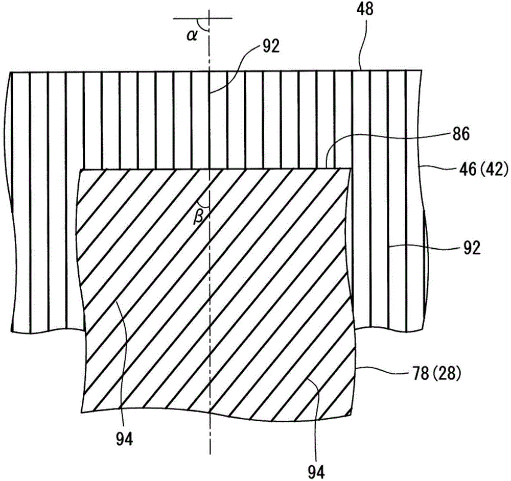
[0106] Tires of Examples 2 to 3 and Comparative Examples 2 to 3 were obtained in the same manner as in Example 1 except that the intersection angle β was shown in Table 1 below.

Embodiment 4~5 and comparative example 4~5

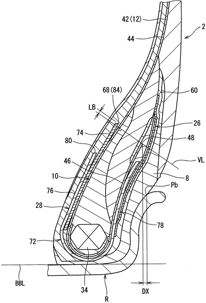
[0108] Tires of Examples 4 to 5 and Comparative Examples 4 to 5 were obtained in the same manner as in Example 1 except that the height Hc of the turned-back portion was adjusted so that the ratio (Hc / Hr) was as shown in Table 2 below.


PUM


Abstract

The invention provides a pneumatic tire (2) capable of improving durability, wherein, in the pneumatic tire (2), a first filling member (26) is closer to the outer side than a tire bead (10) at axial direction; an end portion (48) of a return portion (46) of a tire body cord fabric layer (42) is closer to the inner side than an outer side end (60) of the first filling member (26) at radial direction; a second cord thread (94) of a second filling member (28) is crossed with a tire body cord thread (92) of the tire body cord fabric layer (42); the absolute value of the crossed angle is between 35 degree to 45 degree; with the height of a flange (F) of a wheel ring (R) as a benchmark height, the ratio between the height of the return portion (46) and the benchmark height is between 1.58 to 1.75; with an end portion on the contact surface of the wheel ring (R) as a benchmark position, the end portion (48) of the return portion (46) and the benchmark position are the same at the axial direction, or the end portion (48) of the return portion (46) is closer to the inner side than the benchmark position at the axial direction; and axial direction distance (DX) from the benchmark position to the end portion (48) of the return portion (46) is less than 3 mm.

Description

technical field [0001] The present invention relates to pneumatic tires. Specifically, the present invention relates to pneumatic tires for heavy loads such as trucks and buses. Background technique [0002] When a tire hits the road, it is given a load. As a result, the bead portion is deformed so as to fall toward the flange side of the rim. When the tire is free from the road, the load is removed. As a result, the bead is partially restored. In a tire in a running state, deformation and restoration are repeated at the bead portion. When deformation and restoration are repeated, parts of the bead become heated. Heat can affect the durability of the tire. [0003] The carcass of the tire includes a carcass ply. The carcass ply is folded back around the core of the bead. In some cases, the ends of the carcass ply exist in the bead portion of the tire. When the tire is equipped with a filler, there are ends of the filler in the bead portion. In a tire in a running s...

Claims


Application Information

Patent Timeline
Patent Type & Authority Applications(China)
IPC IPC(8): B60C15/00B60C15/06
Inventor 沼田一起
Owner SUMITOMO RUBBER IND LTD
Learn More