
A positioning device and its calibration component and method

A positioning device and component technology, applied in image data processing, instruments, calculations, etc., can solve problems such as complex calculations, large errors, and inaccuracies, and achieve the effects of accurate determination results, high precision, and convenient operation

Active Publication Date: 2017-12-12
AECC SHENYANG ENGINE RES INST
View PDF3 Cites 0 Cited by
  • Summary
  • Abstract
  • Description
  • Claims
  • Application Information

AI Technical Summary

Problems solved by technology

[0003] The existing technology usually uses mathematical methods to calculate the relationship between distance and camera imaging. Using this method, the error is large, imprecise, and the calculation is complicated

Method used


Image

  • A positioning device and its calibration component and method

Examples


Embodiment Construction

[0020] In order to make the objectives, technical solutions and advantages of the present invention clearer, the technical solutions in the embodiments of the present invention will be described in more detail below in conjunction with the drawings in the embodiments of the present invention. In the drawings, the same or similar reference numerals denote the same or similar elements or elements having the same or similar functions throughout. The described embodiments are some, but not all, embodiments of the invention. The embodiments described below by referring to the figures are exemplary and are intended to explain the present invention and should not be construed as limiting the present invention. Based on the embodiments of the present invention, all other embodiments obtained by persons of ordinary skill in the art without creative efforts fall within the protection scope of the present invention. Embodiments of the present invention will be described in detail below ...


PUM


Abstract

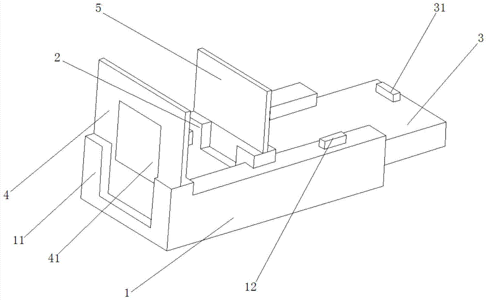
The invention discloses a positioning device, a viewfinder size equipment assembly and a method thereof. The positioning device includes: a positioning device base, one end of which is provided with a mounting groove, and the mounting groove is used to place an observation plate; a movable mounting bracket is arranged on the positioning device base for placing a calibration plate, and the movable mounting bracket can be relatively The long side direction of the positioning device base is moved to adjust the distance between it and the positioning device base; wherein, the projections of the observation plate and the calibration plate coincide, so that the operator observes the overlapped image of the observation plate and the calibration plate from the viewfinder frame of the camera, so that The size of the observation window in the observation plate displayed in the viewfinder of the camera is determined by the scale on the calibration plate. The positioning device of the present invention can determine the imaging size of the camera by determining the size of the observation window, and the determination result is accurate. Compared with the prior art, it has the advantages of high precision, simple structure, and convenient operation.

Description

technical field [0001] The invention relates to the field of cameras, in particular to a positioning device for determining the imaging size of a camera, a calibration component with the positioning device and a method for determining the viewfinder size of a camera using the calibration component. Background technique [0002] When using a particle image velocimeter (PIV for short) to conduct a flow field performance test, the test results required to be given correspond to the specified flow field position inside the test piece. As the imaging component of the PIV system, the CCD camera needs to record the flow field at the measurement position through the observation window. Due to the straight-line propagation of light, the imaging area recorded by the CCD camera is different from the size of the observation window. The distance and relative relationship between the camera, the observation window and the measurement position have a significant impact on the measured are...

Claims


Application Information

Patent Timeline
Patent Type & Authority Patents(China)
IPC IPC(8): G06T7/80
Inventor 金帅王冬冬顾大鹏杨晓李学涛
Owner AECC SHENYANG ENGINE RES INST
Learn More