Eureka AIR delivers breakthrough ideas for toughest innovation challenges, trusted by R&D personnel around the world.

Shear fork type aloft work platform with high-stability driving and steering function

A high-altitude work platform and high-stability technology, applied in the direction of lifting devices, can solve problems such as affecting the user experience, heavy lifting devices, and increasing equipment costs, so as to improve equipment efficiency and safety, improve stability and synchronization. , the effect of increasing the angle limit

Inactive Publication Date: 2015-08-19
ZHEJIANG DINGLI MACHINERY CO LTD
View PDF8 Cites 2 Cited by
  • Summary
  • Abstract
  • Description
  • Claims
  • Application Information

AI Technical Summary

Problems solved by technology

The existing scissor-type aerial work platforms have the following problems: 1) The scissor lifting device is assembled by stacking and intersecting the scissor tubes intersecting each other layer by layer, wherein the scissor tube of the bottom layer is hinged on the On the track wheel, the track wheel can slide back and forth on the chassis along the track to match the up and down lift of the scissor tube
Due to the increasing working height of the existing aerial work platforms, the weight of the lifting device is also increasing, resulting in the lifting cylinder needing to withstand greater working pressure. In order to ensure the stability of the work, it is necessary to set up an auxiliary lifting cylinder. Auxiliary support, resulting in higher equipment costs
2) During the operation of the aerial work platform, the platform operation requires high mobility flexibility. The steering structure of the existing driving wheel has poor stability and synchronization during the steering process, and the rotation angle is limited, which affects the user experience.

Method used


Image

  • Shear fork type aloft work platform with high-stability driving and steering function
  • Shear fork type aloft work platform with high-stability driving and steering function
  • Shear fork type aloft work platform with high-stability driving and steering function

Examples


Embodiment Construction

[0022] The present invention will be further described in detail below in conjunction with the accompanying drawings and examples. The following examples are explanations of the present invention and the present invention is not limited to the following examples.

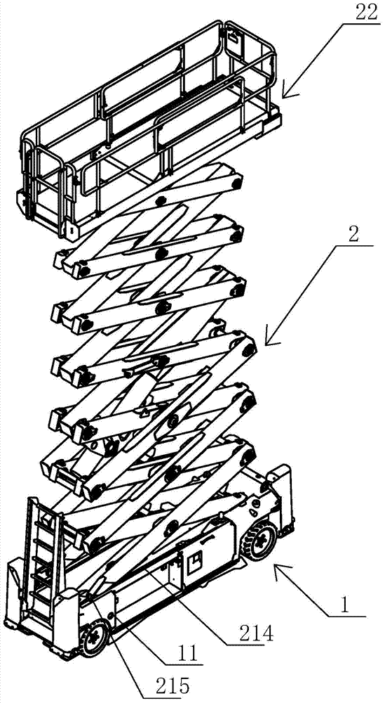
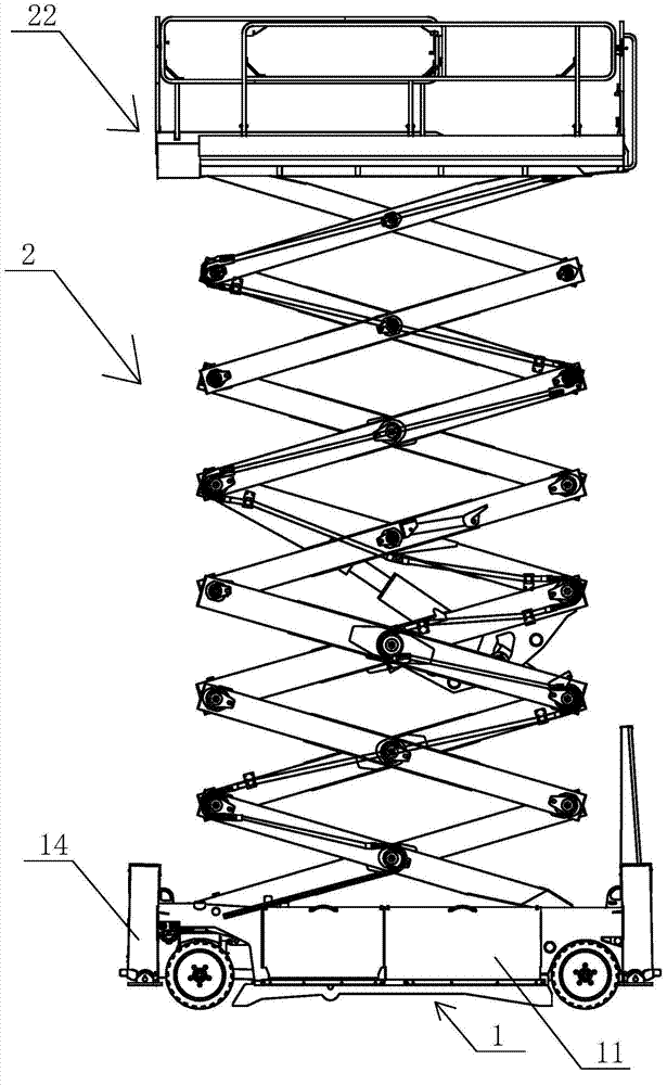
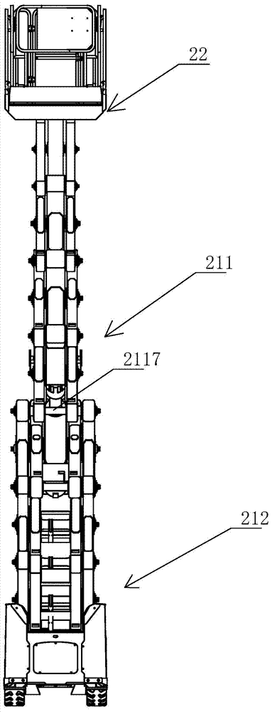
[0023] see Figure 1-Figure 14 In this embodiment, the scissor-type aerial work platform with high-stability driving steering function includes a driving chassis 1 and a lifting device 2, and the driving chassis 1 includes a chassis 11, a driving device 12 and a leg structure 14, and the lifting device 2 includes a scissor lift structure 21 and a working platform 22.

[0024] Described traveling device 12 comprises left steering wheel 121, right steering wheel 122, left wheel frame 123, right wheel frame 124, linkage frame 125, steering oil cylinder 126 and steering bending plate 127, and described left steering wheel 121, right steering wheel 122 respectively Rotation is installed on the left wheel frame 123, the ...


PUM


Abstract

The invention discloses a shear fork type aloft work platform with a high-stability driving and steering function. The shear fork type aloft work platform is characterized by comprising a driving chassis and a lifting device; the driving chassis comprises a chassis body, a driving device and a supporting leg structure; the lifting device comprises a shear fork type lifting structure and a working platform; the shear fork type lifting structure comprises an upper shear fork unit, a lower shear fork unit and a lifting oil cylinder. Through the small-width upper shear fork unit, on the premise of ensuring the lifting height, by decreasing the thickness of the upper shear fork unit, the weight borne by the lifting hydraulic cylinder is reduced, and the efficiency and safety of the device are improved; through the large-width lower shear fork unit, the supporting stability is ensured; the stability and synchronism of the steering process are improved; by forming pits in a steering bent plate, the steering bent plate can be closer to a wheel carrier shaft, and therefore the steering angle limit can be improved, and the use performance is enhanced.

Description

technical field [0001] The invention relates to a scissor-type high-altitude work platform with a high-stability driving steering function. Background technique [0002] Aerial work platform is a product that serves mobile high-altitude operations such as aerial work, equipment installation, and maintenance in various industries. The related products of aerial work platforms mainly include: scissor-type aerial work platforms, vehicle-mounted aerial work platforms, articulating-arm aerial work platforms, self-propelled aerial work platforms, aluminum alloy aerial work platforms, and cylinder-type aerial work platforms. The existing scissor-type aerial work platforms have the following problems: 1) The scissor lifting device is assembled by stacking the scissor tubes intersecting and hinged one by one, and the bottom scissor tube is hinged on the On the track wheel, the track wheel can slide back and forth on the chassis along the track to match the up and down lift of the sc...

Claims


Application Information

Patent Timeline
Patent Type & Authority Applications(China)
IPC IPC(8): B66F11/04
CPCB66F11/042
Inventor 许树根
Owner ZHEJIANG DINGLI MACHINERY CO LTD
Why Eureka
Eureka Blog
Learn More