Sliding block and sliding device

A technology of sliders and mounting grooves, which is applied to shafts and bearings, linear motion bearings, bearings, etc., and can solve problems affecting the performance of parts and sliding force changes, etc.

Active Publication Date: 2015-08-19
BEIJING BORGWARD AUTOMOBILE CO LTD
View PDF5 Cites 2 Cited by
  • Summary
  • Abstract
  • Description
  • Claims
  • Application Information

AI Technical Summary

Problems solved by technology

Because the slider 10 and the friction plate 12 are an integral structure, the sliding force will change with the we

Method used


Image

  • Sliding block and sliding device
  • Sliding block and sliding device
  • Sliding block and sliding device

Examples


Embodiment Construction

[0019] Specific embodiments of the present invention will be described in detail below in conjunction with the accompanying drawings. It should be understood that the specific embodiments described here are only used to illustrate and explain the present invention, and are not intended to limit the present invention.

[0020] In the present invention, unless stated to the contrary, the orientation words used such as "up, down, left, right" usually refer to the direction in the drawing, and do not indicate the direction of the product in the actual application state. direction. "Inside and outside" are relative to the product itself and are relative concepts.

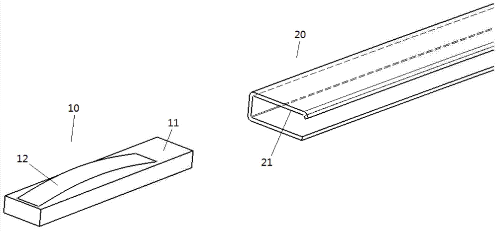
[0021] see first figure 1 , usually, the slider 10 is constrained in the guide rail 20 and relatively slides along the guide rail 20, and the two jointly constitute a sliding device. The slider 10 has a slider matching surface 11 , and the guide rail 20 has a corresponding guide rail matching surface 21 . The frictio...


PUM


Abstract

The invention discloses a sliding block. The sliding block (10) is provided with a friction plate (12) and an adjustment mechanism (13). The friction plate (12) protrudes from a sliding block fitting surface (11) on the sliding block (10), and the height by which the friction plate (12) protrudes from the sliding block fitting surface (11) is adjusted by the adjustment mechanism (13). The invention also discloses a sliding device, which comprises a guide rail (20) and the sliding block (10) sliding along the guide rail, wherein the friction plate (12) and a guide rail fitting surface (21) on the guide rail (20) are in friction fit. The friction plate and the sliding block are a split type structure, and the height by which the friction plate protrudes from the sliding block fitting surface is adjusted by the adjustment mechanism, so that the sliding force can be constantly maintained in a needed range so as to ensure the sliding performance between parts.

Description

technical field [0001] The invention relates to the sliding fit between parts, in particular to a slider and a slider with the slider. Background technique [0002] Between relatively sliding parts, the change of sliding force will affect the performance of the parts. [0003] like figure 1 As shown, the slider 10 and the friction plate 12 are of an integrated structure, the friction plate 12 protrudes from the slider mating surface 11 on the slider 10 , and frictionally fits with the guide rail mating surface 21 on the guide rail 20 . Because the slider 10 and the friction plate 12 are of an integrated structure, the sliding force will change as the wear between the friction plate 12 and the guide rail matching surface 21 will affect the performance of the components. Contents of the invention [0004] The object of the present invention is to provide a slider that can adjust the sliding force between the slider and the guide rail. [0005] Another object of the presen...

Claims


Application Information

Patent Timeline
IPC IPC(8): F16C29/02
Inventor 张永
Owner BEIJING BORGWARD AUTOMOBILE CO LTD
Why Eureka
Try Eureka