
Aligning tool and method for engine testing

A technology for engines and inspection tools, which is applied in the direction of engine testing, machine/structural component testing, and measuring devices. Medium precision, simple and intuitive operation

Active Publication Date: 2015-08-19
BEIJING BORGWARD AUTOMOBILE CO LTD
View PDF6 Cites 9 Cited by
  • Summary
  • Abstract
  • Description
  • Claims
  • Application Information

AI Technical Summary

Problems solved by technology

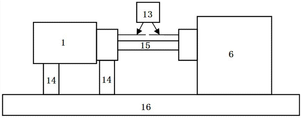
[0004] However, due to the limited space on site, currently some of the bench engines 1 and the dynamometer 6 are centered using a steel ruler with a thick side and a center height, and the method of aligning the middle steel needle 13 is repeatedly adjusted. The alignment process is complicated and requires a certain amount of work. Practical experience, otherwise it is difficult to operate, and the final result is greatly affected by human factors, so it is necessary to improve the current crude alignment device and alignment method

Method used


Image

  • Aligning tool and method for engine testing
  • Aligning tool and method for engine testing
  • Aligning tool and method for engine testing

Examples


Embodiment Construction

[0035] The specific embodiments of the present invention will be described in detail below with reference to the accompanying drawings. It should be understood that the specific embodiments described here are only used to illustrate and explain the present invention, and are not intended to limit the present invention.

[0036] In the present invention, unless stated to the contrary, the used orientation words such as "up, down, top, bottom" generally refer to the directions shown in the drawings or refer to the vertical, perpendicular or gravitational directions The terms used to describe the mutual positional relationship of the various components mentioned above. In addition, unless otherwise stated, "left and right" generally refer to the left and right directions in the horizontal direction of the paper.

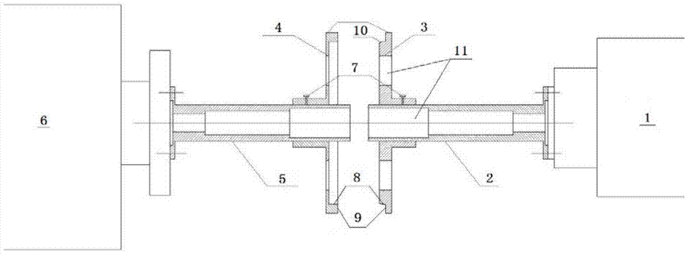
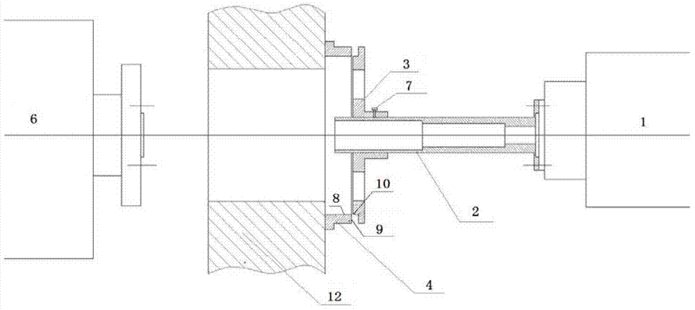
[0037] see figure 2 and image 3 , the present invention firstly provides a centering fixture for engine testing, which includes an engine centering shaft 2, a conv...


PUM


Abstract

The invention discloses an aligning tool and method for engine testing. The aligning tool includes an engine aligning shaft (2), and a convex ridge aligning plate (3) and a concave ridge aligning plate (4) in ridge fit with each other. A fake shaft is connected to the output terminal of an engine (1) in a manner of being coaxial with an engine shaft. One of the two aligning plates is mounted in a manner of being coaxial with a shaft of a dynamometer (6) while the other one is mounted in a rotary sleeving manner of being coaxial with an aligning shaft of the engine. The aligning method includes aligning tool mounting steps, pre-aligning steps, alignment checking steps and fine alignment steps. Deviation between the two shafts is amplified by utilizing the diameters of the aligning plates and alignment precision can be guaranteed through fine processing of the ridges. During alignment operation, pre-alignment can be performed by utilizing a straight edge knife and through rotation and alignment between peripheral ridge faces and alignment between middle end faces are realized through adjusting the engine, so that the alignment process is implemented. The aligning tool and method is simple and direction in operation and high in alignment operation efficiency, and requires little manual experience.

Description

technical field [0001] The invention relates to the field of engine testing, in particular to a centering tool and a centering method for engine testing. Background technique [0002] In the field of engine testing, the alignment results of the shafting will affect the reliability of the engine support and transmission system. Good alignment will not cause additional factors that cause system vibration, ensuring the smooth operation of the engine and the reliability of the test results. [0003] figure 1 It shows a typical engine centering test structure in the prior art, centering by means of a centering steel needle 13 . Wherein, a dynamometer 6 is installed on the horizontal iron 16, and an engine 1 is arranged beside the dynamometer 6. The engine 1 is supported on the horizontal iron 16 by an engine support block 14, and a transmission shaft 15 is connected between the engine 1 and the dynamometer 6. , the power transmission shaft 15 is a cardan shaft. Before carrying...

Claims


Application Information

Patent Timeline
IPC IPC(8): G01M15/02G01B5/25
Inventor 李耿隋长俊
Owner BEIJING BORGWARD AUTOMOBILE CO LTD
Learn More