Roll changing mechanism for working roll of rolling mill

A technology of work roll and roll structure, which is applied in the direction of metal rolling stand, metal rolling mill stand, metal rolling, etc., can solve the problems of low work efficiency, time-consuming and labor-intensive work roll, etc., and achieve convenient roll change and easy roll change , the effect of high promotion value

Inactive Publication Date: 2015-08-26
MCC SFRE HEAVY IND EQUIP
View PDF5 Cites 5 Cited by
  • Summary
  • Abstract
  • Description
  • Claims
  • Application Information

AI Technical Summary

Problems solved by technology

[0003] The purpose of the present invention is to provide a roll changing structure for the working rolls of a rolling mill, which solves the problems in the prior art that when changing the working rolls, it is necessary to manually place contour blocks, the replacement of the working rolls is time-consuming and laborious, and the problem of low work efficiency

Method used


Image

  • Roll changing mechanism for working roll of rolling mill
  • Roll changing mechanism for working roll of rolling mill
  • Roll changing mechanism for working roll of rolling mill

Examples


Embodiment Construction

[0015] The present invention will be described in detail below in conjunction with the accompanying drawings and specific embodiments.

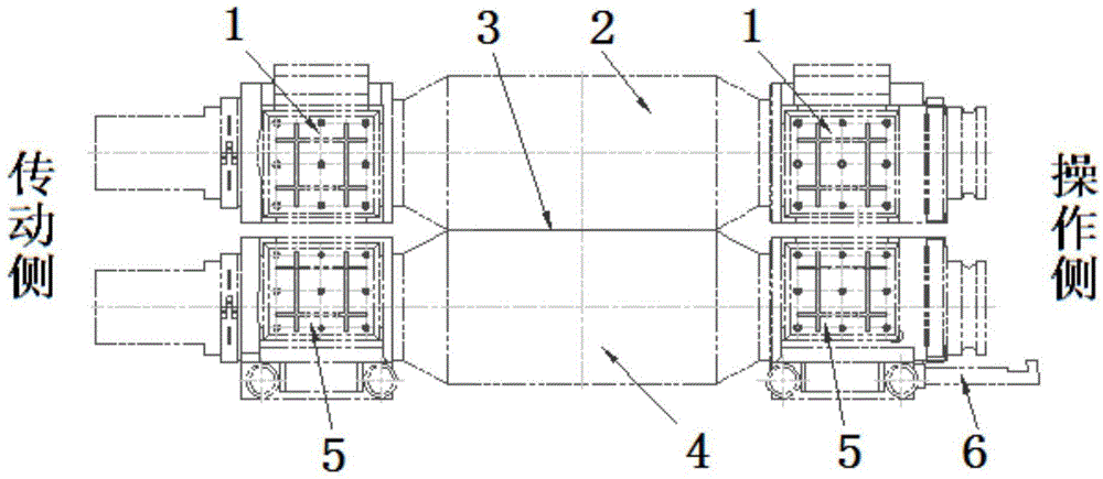
[0016] refer to figure 1 , figure 2 , the structure of the prior art (before improvement) is that an upper bearing seat 1 and a lower bearing seat 5 are respectively arranged on the working side and the operating side mounting seat, and the upper bearing seat 1 and the lower bearing seat 5 are arranged parallel to the axis line up and down; The upper bearing housing 1 and the lower bearing housing 5 are respectively worn with an upper working roll 2 and a lower working roll 4, between the roll surfaces of the upper working roll 2 and the lower working roll 4 is a rolled strip 3, the upper working roll 2, the lower working roll The work roll 4 is pulled out by the roll changing hook 6 when taking it out.

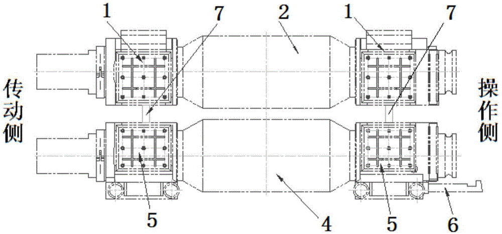
[0017] When the work roll needs to be replaced, such as figure 2 As shown, first use the balance cylinder (not shown) to lift the uppe...


PUM


Abstract

The invention discloses a roll changing mechanism for a working roll of a rolling mill. An upper bearing seat and a lower bearing seat are arranged on an installing seat of a work side and an installing seat of an operating side respectively. The shaft axis of the upper bearing seat and the shaft axis of the lower bearing seat are arranged in parallel. An upper working roll and a lower working roll penetrate through the upper bearing seat and the lower bearing seat respectively. An equal-height hinge pin is fixedly arranged on the upper surface of the lower bearing seat at the working side. A depth hole and a shallow hole are formed in the bottom face of the upper bearing seat at the working side. Another equal-height hinge pin is fixedly arranged on the upper surface of the lower bearing seat at the operating side. A depth hole and a shallow hole are formed in the bottom face of the upper bearing seat at the operating side. According to the structure of the roll changing mechanism for the working roll of the rolling mill, the equal-height hinge pin is included on the upper surface of the lower bearing seat, and two holes with different depths are formed in the bottom of the upper bearing seat correspondingly, the function of adding a height-equal block manually is realized, and fast, convenient and safe roll changing is realized.

Description

technical field [0001] The invention belongs to the technical field of metallurgical rolling equipment, can meet the rapid roll change of work rolls of a four-high rolling mill, and relates to a work roll change structure of a rolling mill. Background technique [0002] In rolling mill equipment, work roll change is an indispensable process. In four-high reversible hot and cold rolling mills, since the upper work roll has no track, it can only be carried out by the lower work roll when changing rolls. When changing rolls, the upper and lower work rolls must not touch each other. Therefore, before changing the work rolls, it is necessary to place a contour pad between the upper and lower bearing seats on the transmission side and the operation side. block, so that the bearing housings can contact each other, and smoothly pull out the upper and lower work rolls together. Due to the limitation of the position of the transmission side, it is extremely inconvenient, time-consumin...

Claims


Application Information

Patent Timeline
Patent Type & Authority Applications(China)
IPC IPC(8): B21B31/08B21B31/10
Inventor 郭瑞林刘德华张林姬明刚
Owner MCC SFRE HEAVY IND EQUIP
Why Eureka
Try Eureka