Spindle box movable type milling tool with main shaft with five-shaft structure

A shaft structure and machine tool technology, which is applied to metal processing machinery parts, other manufacturing equipment/tools, metal processing equipment, etc., can solve the problems that affect the forming efficiency of the workpiece, and the forming time of the workpiece is not well optimized, so as to achieve the forming time Optimize, avoid resistance, and avoid time-wasting effects

Inactive Publication Date: 2015-08-26
NANJING JIANKE MACHINERY
View PDF7 Cites 0 Cited by
  • Summary
  • Abstract
  • Description
  • Claims
  • Application Information

AI Technical Summary

Problems solved by technology

[0004] The purpose of the present invention is to provide a center-type turning and milling machine tool with a five-axis structure on the positive axis, so as to solve the problem that the tools on the center-type turning-milling machine tool in the prior art are installed on the same part, which causes each tool to work. The processing can only be carried out after the previous tool is finished. The mutual limitations of the tools lead to the poor optimization of the workpiece forming time and the technical defect that affects the forming efficiency of the workpiece.

Method used


Image

  • Spindle box movable type milling tool with main shaft with five-shaft structure
  • Spindle box movable type milling tool with main shaft with five-shaft structure
  • Spindle box movable type milling tool with main shaft with five-shaft structure

Examples


Embodiment 1

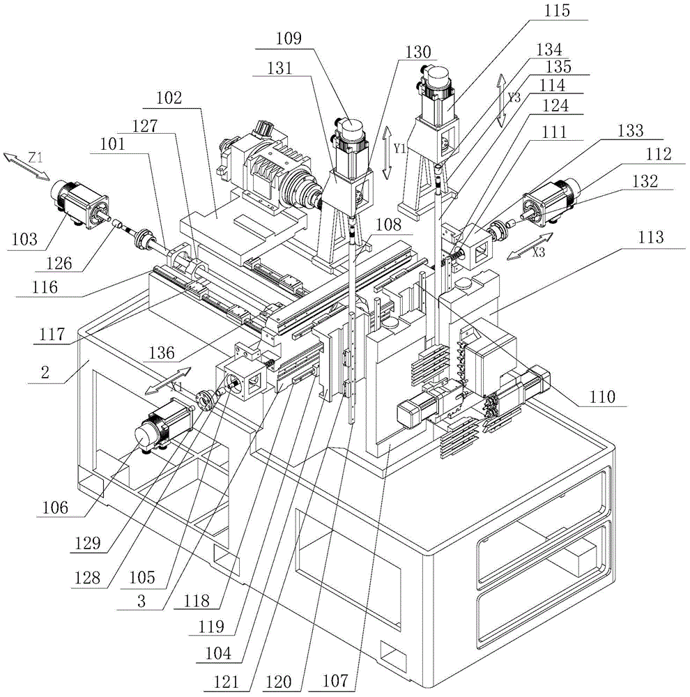
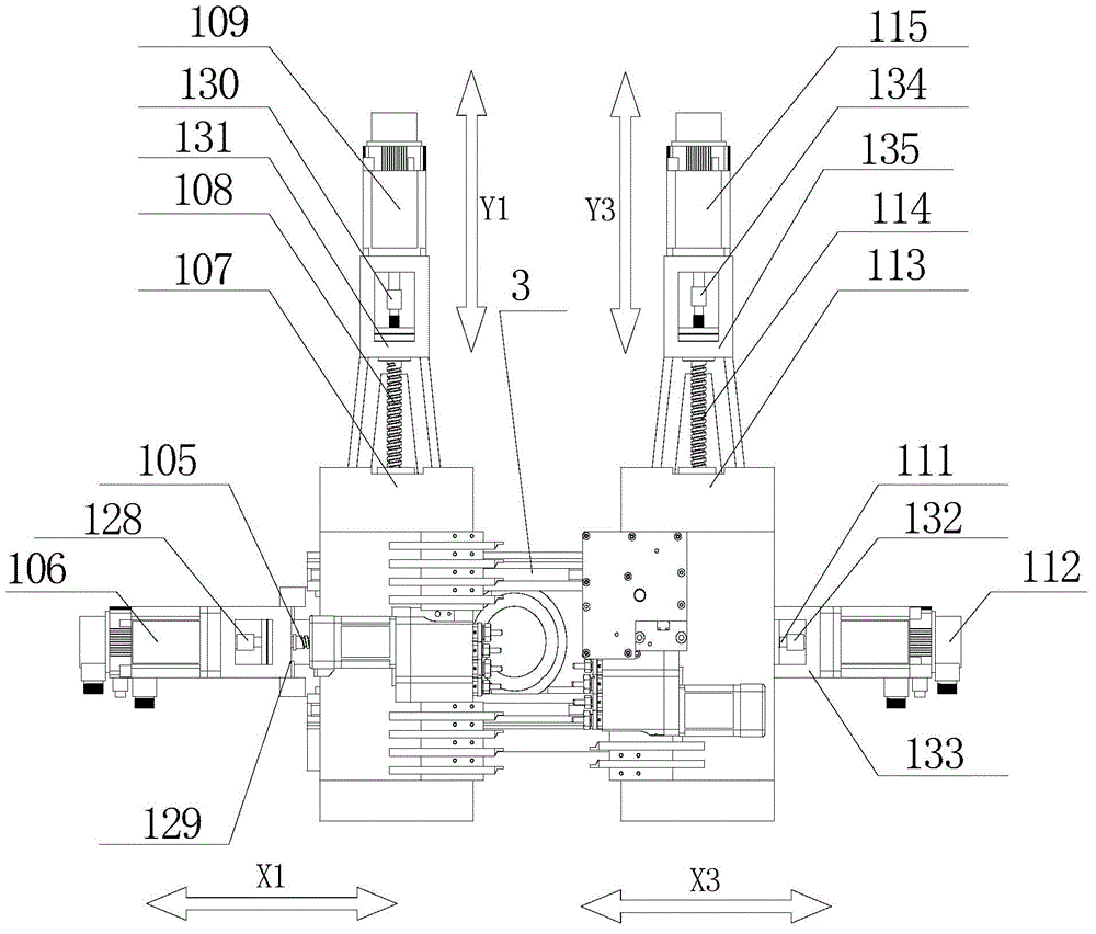
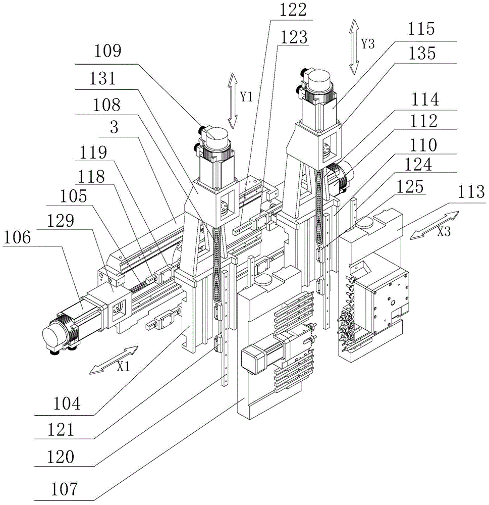
[0058] Such as figure 1 , figure 2 with image 3 The shown center-type turning and milling machine tool with a five-axis structure on the positive axis includes a bed 2, which is set on the bed 2 and consists of a first column, a second column, and a third column arranged along the X-axis direction. 3. Positive axis group consisting of X1 axis group, Y1 axis group, Z1 axis group, X3 axis group, and Y3 axis group. A through hole is opened on the second column, and a guide sleeve or no guide sleeve is arranged in the through hole. The column in the present invention can be fixed on the bed with bolts, or can be integrally manufactured with the bed when manufacturing the bed. forming.

[0059] The Z1-axis group includes a Z1-axis slide plate 102 arranged on the bed 2, two Z1-axis rails are arranged in parallel on the bed 2, and a Z1-axis slide block 117 is set on the bottom of the Z1-axis slide plate 102 , the Z1-axis slider 117 is matched with the Z1-axis rail. The bottom ...

Embodiment 2

[0068] The difference between this embodiment and Embodiment 1 is that the first tool mount 107 is the first turret, and the Y1 axis rail that forms a sliding pair with the Y1 axis slider is installed on the first turret; the second tool mount 113 is the second The turret, the second turret is installed with the Y3-axis rail that forms a sliding pair with the Y3-axis slider, and knives are installed on the first turret and the second turret. The rest of the structure is the same as that of Embodiment 1, see Embodiment 1 for details , not detailed here. At this time, the turret rotates 360°, and the tools at each station of the turret can be changed flexibly to realize the processing of the workpiece. This assembly structure not only saves space, but also can be installed on the turret. Increase the variety and quantity of cutting tools, power heads, etc. to a certain extent, and the disc design is conducive to chip removal when the tool is processing parts, and to a greater ex...

Embodiment 3

[0070] Compared with Embodiment 1, the first tool mount 107 of this embodiment is composed of the Y1-axis slide plate and the first turret. The difference from Embodiment 1 is that the first turret is installed on the Y1-axis slide plate. Install the tool; the second tool mounting seat 113 is composed of a Y3-axis slide plate and a second turret. The difference from Embodiment 1 is that the second turret is installed on the Y3-axis slide plate, and the tool is installed on the second turret. The 360-degree rotation of the turret and the second turret realizes tool change, saving time for tool change. The rest of the structure of this embodiment is the same as that of Embodiment 1, and will not be described in detail here. At this time, the turret rotates 360°, and the tools at each station of the turret can be changed flexibly to realize the processing of the workpiece. This assembly structure not only saves space, but also can be installed on the turret. Increase the variety...


PUM


Abstract

The invention discloses a spindle box movable type milling tool with a main shaft with a five-shaft structure. The spindle box movable type milling tool comprises a tool body, a stand column, and a main shaft set. The main shaft set is arranged on the tool body and composed of an X1 shaft set, a Y1 shaft set, a Z1 shaft set, an X3 shaft set and a Y3 shaft set; the Z1 shaft set comprises a Z1 shaft lead screw, a Z1 shaft servo motor and a tool main shaft; the Z1 shaft servo motor drives the tool main shaft through the Z1 shaft lead screw to slide on the tool body in the Z shaft direction in a reciprocating mode; the X1 shaft set comprises an X1 shaft sliding plate, an X1 shaft lead screw and an X1 shaft servo motor; the X1 shaft sliding plate is installed at one end of the stand column in a sliding mode; the Y1 shaft set comprises a first cutter installation base, a Y1 shaft lead screw and a Y1 shaft servo motor; a Y1 shaft sliding plate is installed on the X1 shaft sliding plate in a sliding mode; the X3 shaft set comprises an X3 shaft sliding plate, an X3 shaft lead screw and an X3 shaft servo motor; the Y3 shaft set comprises a second cutter installation base, a Y3 shaft lead screw and a Y3 shaft servo motor. The spindle box movable type milling tool has the advantage of overcoming the technical defect that due to mutual limitation of cutters in the prior art, the forming time of workpieces is not well optimized, and the forming efficiency of workpieces is affected.

Description

technical field [0001] The invention relates to a center turning and milling machine tool with a five-axis structure on the positive axis. Background technique [0002] In the existing centering machine market, there has been research on the technology of machine tool motion axes, and the most widely used is the three-axis centering machine with positive axis structure consisting of X1 axis group, Y1 axis group, and Z1 axis group. The Z1-axis slide plate of the three-axis centering machine has a machine tool positive spindle. The positive spindle is a through hole. The tail end of the positive spindle is connected to the feeder. The workpiece material is placed on the feeder. After the worker edits the program, the feeder is in order. Continuously feed the material into the positive spindle of the machine tool, the machine tool spindle clamps the bar and moves back and forth on the Y axis, and cooperates with the guide sleeve structure of the machine tool (the guide sleeve c...

Claims


Application Information

Patent Timeline
Patent Type & Authority Applications(China)
IPC IPC(8): B23P23/02B23Q5/40
CPCB23P23/02B23Q5/40B23Q5/402
Inventor 王建飞
Owner NANJING JIANKE MACHINERY
Why Eureka
Try Eureka