Core-passing turning-milling machine tool of five-shaft structure

A shaft structure and machine tool technology, which is applied in the direction of metal processing machinery parts, other manufacturing equipment/tools, large fixed members, etc., can solve the problems that affect the forming efficiency of workpieces, and the forming time of tools and workpieces is not well optimized, so as to achieve forming Time optimization, avoiding resistance, and ensuring the effect of high-precision rotation

Inactive Publication Date: 2015-09-02
NANJING JIANKE MACHINERY
View PDF10 Cites 0 Cited by
  • Summary
  • Abstract
  • Description
  • Claims
  • Application Information

AI Technical Summary

Problems solved by technology

[0004] The purpose of the present invention is to provide a five-axis structure of the center turning and milling machine tool, which solves the problem that in the prior art, the tools on the center turning and milling machine are all installed on the same part, so each tool must wait for the first time when it is working. A tool can only be processed after it has been processed. The mutual limitations of the tools lead to poor optimization of the forming time of the workpiece, which affects the technical defect of the forming efficiency of the workpiece.

Method used


Image

  • Core-passing turning-milling machine tool of five-shaft structure
  • Core-passing turning-milling machine tool of five-shaft structure
  • Core-passing turning-milling machine tool of five-shaft structure

Examples


Embodiment 1

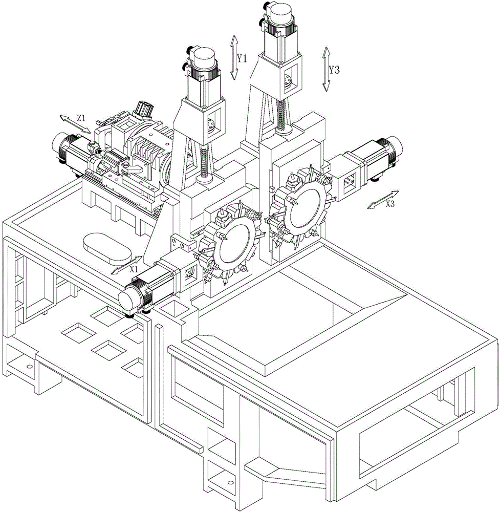
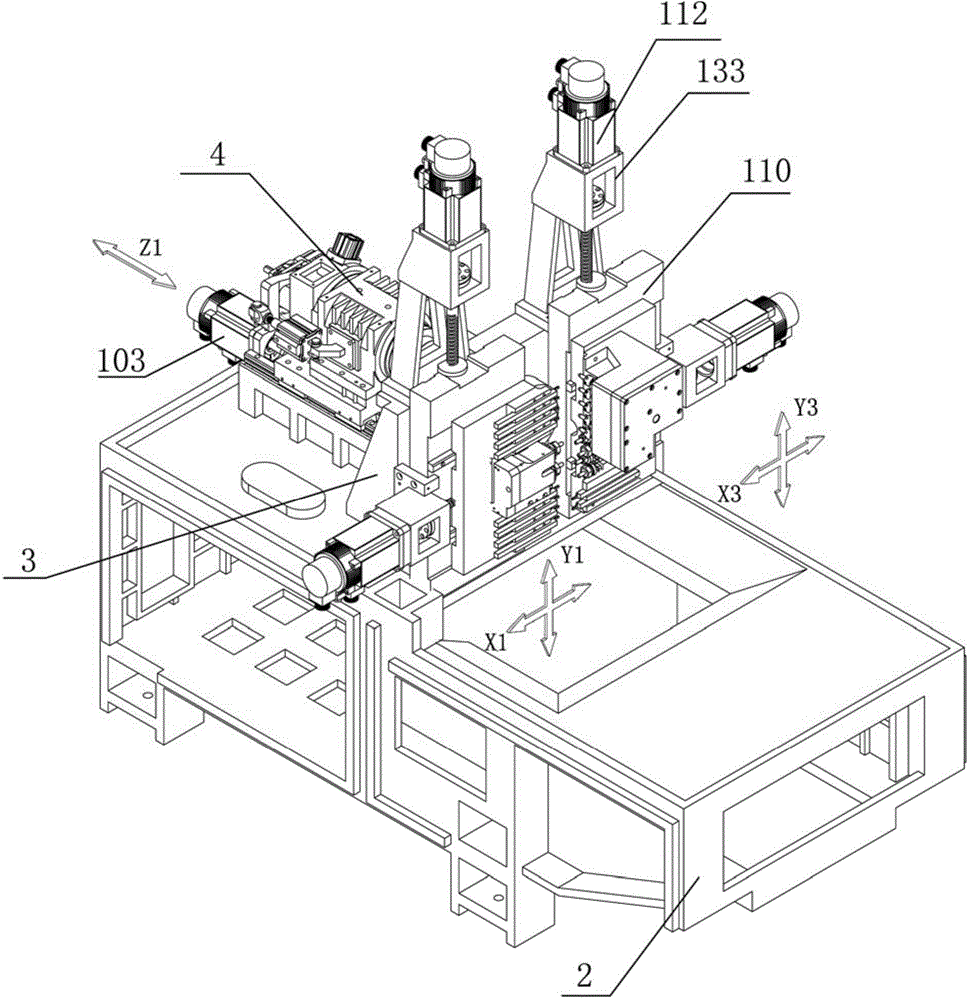
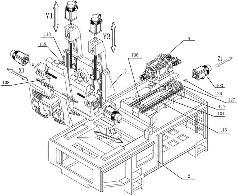
[0057] like figure 1 , figure 2 and image 3 The shown center turning and milling machine tool with a five-axis structure on the positive axis includes a bed 2 and a column 3 arranged on the bed 2. The column consists of a first column arranged along the X-axis direction, a second The column and the third column are composed of a positive axis group consisting of the X1 axis group, the Y1 axis group, the Z1 axis group, the Y3 axis group and the X3 axis group. The second column is provided with a through hole, and a guide sleeve structure or no guide sleeve structure is set in the through hole. The guide sleeve structure and the no guide sleeve structure in the present application are all prior art, and are commonly used in this field. components, which are not described in detail here. In the present invention, the column 3 can be detachably installed on the bed with bolts, or can be integrally formed with the bed when the bed is manufactured.

[0058] The Z1-axis group i...

Embodiment 2

[0067] The structure of this embodiment is basically the same as that of Embodiment 1, the difference is that the first tool mounting seat 107 is the first turret, the second tool mounting seat 113 is the second turret, and the X1 axis of the sliding pair is formed with the X1 axis rail 120 The slide block 121 is installed on the first turret; the X3-axis slide block 125 forming a sliding pair with the X3 axis rail 124 is installed on the second turret, and tools are installed on the first turret and the second turret. The 360° rotation of the turret and the second turret realizes the tool change, and the rest of the same structure as the first embodiment refers to the first embodiment, which will not be described in detail here. At this time, the turret rotates 360°, and the tools at each station of the turret can be changed flexibly to realize the processing of the workpiece. This assembly structure not only saves space, but also can be installed on the turret. Increase the ...

Embodiment 3

[0069] The structure of this embodiment is basically the same as that of Embodiment 1, the difference is that the first tool mount 107 is composed of the X1-axis slide plate and the first turret mounted on the X1-axis slide plate, and forms the X1 axis of the sliding pair with the X1-axis rail 120 The slide block 121 is installed on the X1-axis slide plate, and the first turret is installed on the X1-axis slide plate through bolts; the second tool mount 113 is composed of the X3-axis slide plate and the second knife mounted on the X3-axis slide plate. The tower constitutes, and the X3-axis slider 125 that constitutes a sliding pair with the X3-axis rail 124 is installed on the X3-axis slide plate, and the second turret is installed on the X3-axis slide plate through bolts, and the first turret and the second turret For installing the tool, use the 360° rotation of the first turret and the second turret to realize the tool change, and refer to the first embodiment for the rest o...


PUM


Abstract

The invention discloses a core-passing turning-milling machine tool of a five-shaft structure. The core-passing turning-milling machine tool comprises a machine body, an upright, and a positive shaft group arranged on the machine body and composed of an X1 shaft group, a Y1 shaft group, a Z1 shaft group, an X3 shaft group and a Y3 shaft group; the Z1 shaft group comprises a Z1 shaft lead screw, a Z1 shaft sliding plate and a Z1 shaft servo motor, and the Z1 shaft sliding plate is mounted on the machine body of the machine tool in a sliding manner; the X1 shaft group comprises an X1 shaft sliding plate, an X1 shaft lead screw and an X1 shaft servo motor, and the X1 shaft sliding plate is mounted on the machine body of the machine tool in a sliding manner; the Y1 shaft group comprises a first cutting tool mounting base, a Y1 shaft lead screw and a Y1 shaft servo motor; a Y1 shaft sliding plate is mounted on the X1 shaft sliding plate in a sliding manner; the X3 shaft group comprises an X3 shaft sliding plate, an X3 shaft lead screw and an X3 shaft servo motor; the Y3 shaft group comprises a second cutting tool mounting base, a Y3 shaft lead screw and a Y3 shaft servo motor. The core-passing turning-milling machine tool of the five-shaft structure has the beneficial effects that the workpiece forming time is not well optimized due to mutual limitations of cutting tools in the prior art and the workpiece forming efficiency is affected.

Description

technical field [0001] The invention relates to a center turning and milling machine tool with a five-axis structure. Background technique [0002] In the existing center turning and milling machine tool market, there has been research on the technology of machine tool motion axes, and the most widely used is the three-axis positive axis structure consisting of X1 axis group, Y1 axis group, and Z1 axis group. Scheming. The Z1-axis slide plate of the three-axis centering machine has a machine tool main shaft. The main shaft of the machine tool is a through hole. The tail end of the machine tool main shaft is connected to the feeder. The raw material of the workpiece is placed on the feeder. After the worker edits the program, the feeder Continuously and uninterruptedly feed the material into the main spindle of the machine tool in sequence, the positive spindle of the machine tool holds the bar and moves back and forth on the Y axis, and cooperates with the guide sleeve stru...

Claims


Application Information

Patent Timeline
Patent Type & Authority Applications(China)
IPC IPC(8): B23Q1/62B23Q5/40B23P23/02
CPCB23Q1/62B23P23/02B23Q5/40
Inventor 王建飞
Owner NANJING JIANKE MACHINERY
Why Eureka
Try Eureka