

Visual debugging of robotic tasks
A robot and robot system technology, applied in the direction of instruments, manipulators, program-controlled manipulators, etc., can solve problems such as difficult reorganization of control software
- Summary
- Abstract
- Description
- Claims
- Application Information
AI Technical Summary
Problems solved by technology
Method used
Image

Examples
Embodiment Construction
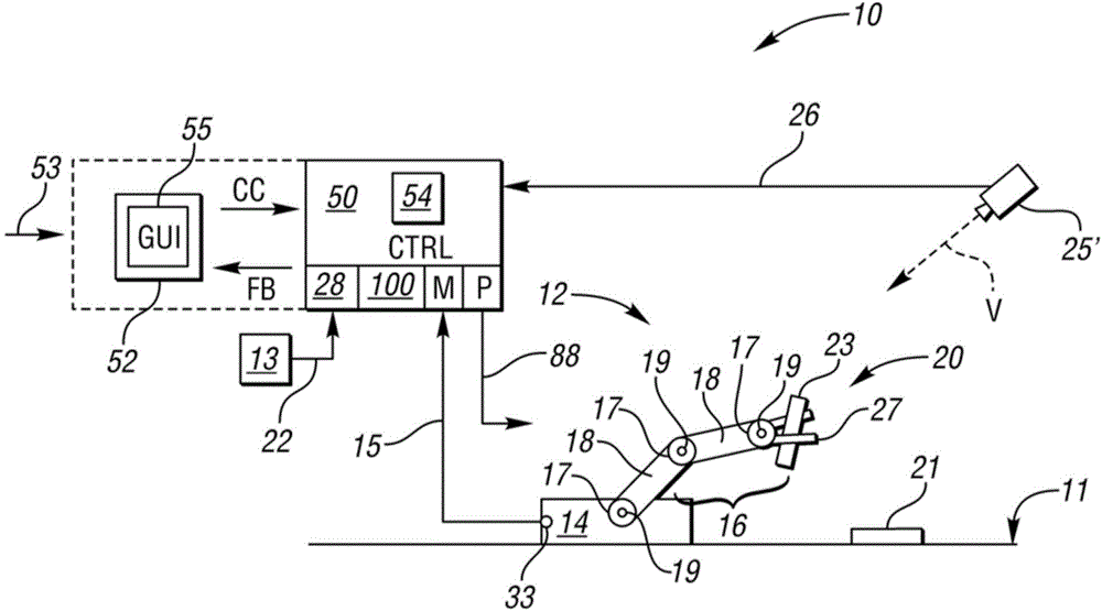
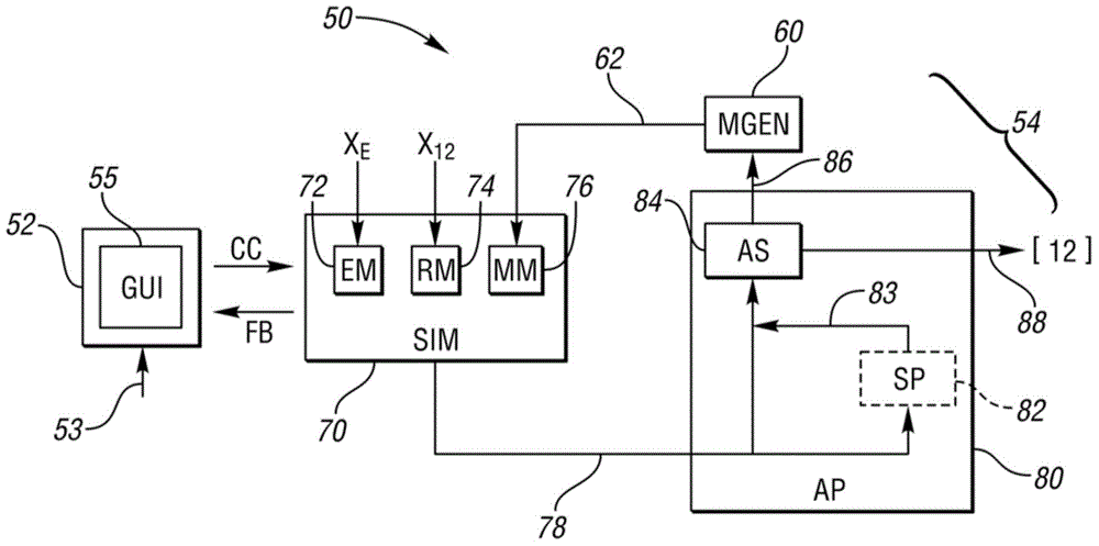
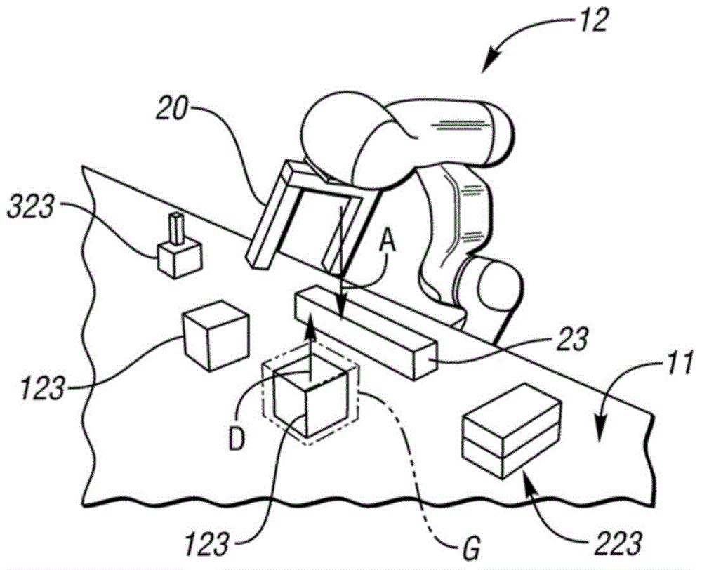
[0017] Referring to the drawings, in which like reference numerals indicate like or similar components throughout the several views, an exemplary robotic system 10 is shown in figure 1 is schematically shown with a robot 12 . In an exemplary embodiment, robot 12 may be a manufacturing robot operable to perform material manipulation or assembly tasks, such as a 6-axis robot type known in the art, or an autonomous dexterous robot having at least 6 degrees of freedom. The motion of the robot 12 can be visually debugged via the controller 50 (CTRL) as described below. Controller 50 executes instructions implementing method 100, an example of which is shown in Figure 5 middle. An exemplary "virtual world" graphic or visual debug screen of graphical user interface (GUI) 52 is shown at Figure 2-4 , each of these drawings will be described below.
[0018] As is known in the art, conventional end effectors are designed to operate in a highly structured work environment with a min...
PUM
 Abstract
Description
Claims
Application Information