Cloud computing annularly-arranged disaster tolerance system

A cloud computing and disaster recovery technology, applied in the field of cloud computing, can solve problems such as failure to form cloud platform functions, cloud platform data economy, security, automatic backup, bottlenecks in the development of disaster recovery cloud platforms, etc.

Inactive Publication Date: 2015-08-26
武汉市天下春商贸有限公司
View PDF0 Cites 0 Cited by
  • Summary
  • Abstract
  • Description
  • Claims
  • Application Information

AI Technical Summary

Problems solved by technology

[0002] The cloud platform is the development trend of the Internet. The disaster recovery of the existing cloud platform is additionally configured according to the needs of customers, which fails to form the natural functions of the cloud platform. Human beings have entered the era of frequent disasters. Disasters are increasingly becoming the bottleneck of cloud platform development

Method used


Image

  • Cloud computing annularly-arranged disaster tolerance system
  • Cloud computing annularly-arranged disaster tolerance system
  • Cloud computing annularly-arranged disaster tolerance system

Examples


Embodiment 1

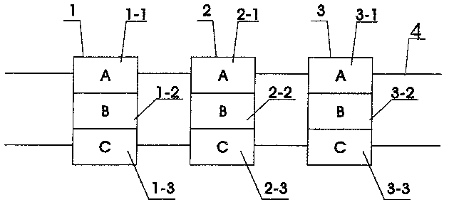
[0012] Embodiment 1: Schematic diagram of the backup function of the present invention

[0013] In the figure, 1 is sub-center 1; 2 is sub-center 2; 3 is sub-center 3; the sub-centers are connected by line 4. Each of the three sub-centers is physically divided into three zones and the rings correspond to each other, that is, sub-center 1’s 1-zone 1-1 corresponds to sub-center 2’s 1-zone 2-1, sub-center 3’s 1 zone 3-1; sub-center 1 The 2 divisions 1-2 of the sub-center 2 correspond to the 2 divisions 2-2 of the sub-center 2 and the 2 divisions 3-2 of the sub-center 3; the 3 divisions 1-3 of the sub-center 1 correspond to the 3 divisions 2-3 and 3 The 3 partitions 3-3 (see the labels A, B, C), when a sub-center such as A is running, the corresponding partition A of the other two sub-centers is synchronous or backed up, so that the data is divided into three places , forming a backup. This kind of partition corresponds to the ring setting, which can not only make full use of su...

Embodiment 2

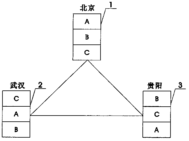
[0014] Embodiment 2: Schematic diagram of the disaster recovery function of the present invention

[0015] Sub-center 1 is built in Beijing, Sub-center 2 is built in Wuhan, and Sub-center 3 is built in Guiyang. Sub-center 1, Sub-center 2, and Sub-center 3 are divided into three areas, A, B, and C, which correspond to each other (intentionally misplaced in the figure) The positions of A, B, and C indicate that the partitions are not consistent on the surface, but corresponding in essence). When the B area of ​​sub-center 1 is running, the B areas of sub-centers 2 and 3 are also running synchronously or in backup. If a disaster occurs in any one place, The data in the other two places are backed up, so that the security of the cloud platform data is guaranteed.

Embodiment 3

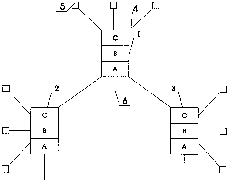
[0016] Embodiment 3: Schematic diagram of the application function of the present invention

[0017] Sub-centers 1, 2, and 3 are respectively connected to terminal 5 through wired and wireless connections. Sub-centers 1, 2, and their respective partitions are ring-located to form disaster recovery units. One disaster recovery unit or multiple disaster recovery units are wired , Wireless 6 forms a cloud platform, which has brand-new functions of resource saving, backup, and disaster recovery.

[0018] The above-mentioned partitioning, synchronous operation, backup, etc. can be realized through the scientific setting and standardized construction of cloud computers, cloud platform management system, and cloud technologies such as HA, SOA, and CDP.


PUM


Abstract

The invention relates to a cloud computing annularly-arranged disaster tolerance system. The cloud computing annularly-arranged disaster tolerance system is characterized in that the cloud computing annularly-arranged disaster tolerance system comprises more than one cloud data sub center; the sub centers are annularly arranged at different location; each sub center is divided into more than one region correspondingly; and therefore, disaster tolerance units can be formed. With the cloud computing annularly-arranged disaster tolerance system adopted, a cloud platform can have automatic backup and disaster tolerance functions, and requirements of the society for the cloud platform can be satisfied.

Description

technical field [0001] The invention relates to cloud computing, in particular to a cloud computing disaster recovery environment which can conveniently, save resources, and automatically perform cloud data backup and disaster recovery. Background technique [0002] The cloud platform is the development trend of the Internet. The disaster recovery of the existing cloud platform is additionally configured according to the needs of customers, which fails to form the natural functions of the cloud platform. Human beings have entered the era of frequent disasters. Disasters have increasingly become the bottleneck of cloud platform development. Contents of the invention [0003] The purpose of the present invention is to overcome the deficiencies of the prior art and provide a cloud computing ring for disaster recovery. On the basis of not increasing the sub-centers, the cloud platform has the functions of backup and disaster recovery by physically correspondingly partitioning ...

Claims


Application Information

Patent Timeline
Patent Type & Authority Applications(China)
IPC IPC(8): H04L29/08G06F11/14
CPCG06F11/1464G06F11/1469H04L67/1097H04L69/40
Inventor 毛千旗
Owner 武汉市天下春商贸有限公司
Why Eureka
Try Eureka