Movable flood control dam for cities

A technology for flood control dams and cities, which is applied in water conservancy projects, sea area projects, coastline protection, etc., and can solve problems such as short service life and inconvenient use of fixed dams

Inactive Publication Date: 2015-09-02
YANTAI SUNNY RUBBER
View PDF8 Cites 1 Cited by
  • Summary
  • Abstract
  • Description
  • Claims
  • Application Information

AI Technical Summary

Problems solved by technology

[0003] The purpose of the present invention is to solve the disadvantages of inconvenient use and short service life of the fixed dam existing in the above-mentioned prior art, and to provide an urban movable flood control dam that is convenient to use and has a long service life.

Method used


Image

  • Movable flood control dam for cities
  • Movable flood control dam for cities
  • Movable flood control dam for cities

Examples


Embodiment 1

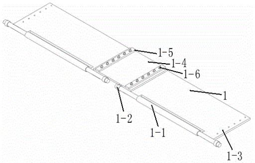
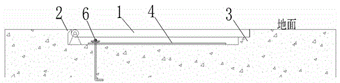
[0022] The urban active flood control dam of present embodiment, with reference to attached figure 1 , 2 , 3, 6, the water retaining height is 1 meter, and the flood control dam includes a flood control plate 1 and a supporting device, both of which are placed in a concave groove, and one side of the concave groove is provided with a conical foundation support frame 2, and the concave The bottom of the shaped groove and the other side are equipped with a flood plate bracket 3, and the other side top of the concave groove is stepped.

[0023] The flood control plate 1 is a flat plate structure, one side of which is provided with a bottom shaft 1-1, the two ends of the bottom shaft 1-1 are equipped with a rotating device 1-2, the two ends of the flood control plate 1 are provided with bolt holes 1-3, and the adjacent flood control plate Room 1 is connected with a rubber plate 1-4, and the two ends of the rubber plate 1-4 are respectively connected and fixed to the flood control...

Embodiment 2

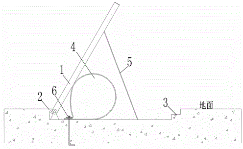
[0027] The urban active flood control dam of present embodiment, with reference to attached Figure 4 , 5 , 7, its water retaining height is 1.5 meters, and the flood control dam includes a flood control plate 1 and a supporting device, both of which are placed in a concave groove, and one side of the concave groove is provided with a conical foundation support frame 2 at the top, and the concave groove The bottom and the other side are equipped with a flood plate bracket 3, and the top of the other side of the concave groove is stepped.

[0028] The flood control plate 1 is a flat plate structure, one side of which is provided with a bottom shaft 1-1, the two ends of the bottom shaft 1-1 are equipped with a rotating device 1-2, the two ends of the flood control plate 1 are provided with bolt holes 1-3, and the adjacent flood control plate One room is connected and fixed by hinges and bolt holes.

[0029] The interconnected flood control panels 1 are hard-connected to the fl...


PUM


Abstract

The invention relates to a hydraulic building device, in particular to a movable flood control dam for cities. The movable flood control dam comprises a flood control plate and a supporting device which are disposed in a groove in the shape of a Chinese character 'ao', a foundation supporting frame with a conical top is arranged on one side of the ao-shaped groove, flood control plate brackets are mounted at the bottom and on one side of the ao-shaped groove, the top of the other side of the ao-shaped groove is in the shape of a step, the floor control plate is fixed on the flood control plate brackets by means of hard connection, a fixing end of the flood control plate is matched with the top of the foundation supporting frame while the tail end of the same is fixed at the upper end of the step of the ao-shaped groove in a clamped manner, the floor control plate is fixed in the ao-shaped groove in a clamped manner and is flush with the ground, and the supporting device is arranged on the lower portion of the flood control plate. The flood control plate and the supporting device are matched with the ao-shaped groove in corresponding shape, the flood control plate is erected to withstand flood at a flood stage and fixed in the ao-shaped groove in the ground in a clamped manner at a normal stage, and the movable flood control dam is flush with the ground, thereby being attractive, conducive to maintaining normal life of the cities and free of causing inconvenience to people's life.

Description

technical field [0001] The invention relates to a hydraulic construction device, in particular to an urban movable flood control dam. Background technique [0002] At present, cities usually have flood control plans for rainy seasons, especially in urban areas with more rain in the south. Flood control dams are usually required for low-lying areas that are prone to waterlogging, so as to prevent damage to buildings and roads on the shore when the seaside high tide or river floods and pedestrian injury. And because the flood control dam is not needed most of the time, the use of the fixed flood control dam is extremely inconvenient. Most of the time it occupies a certain area, affecting traffic and play, and the long-term wind and sun will cause certain natural damage to the flood control dam, shortening the service life of the flood control dam. service life. Therefore, a flood control dam that is movable, convenient to use and has a long service life is urgently nee...

Claims


Application Information

Patent Timeline
Patent Type & Authority Applications(China)
IPC IPC(8): E02B7/40E02B7/20
Inventor 洪志强李玲杨孝栋
Owner YANTAI SUNNY RUBBER
Why Eureka
Try Eureka