Optimized configuration method of voltage sag monitoring node

A technology for monitoring nodes and optimizing configuration, which is applied in the direction of fault location, etc.

Active Publication Date: 2015-09-02
STATE GRID SICHUAN ECONOMIC RES INST +1
View PDF4 Cites 18 Cited by
  • Summary
  • Abstract
  • Description
  • Claims
  • Application Information

AI Technical Summary

Problems solved by technology

[0016] What the present invention aims to solve is the problem that there is a monitoring blind area in the existing optimal configuration method for voltage sag monitoring nodes

Method used


Image

  • Optimized configuration method of voltage sag monitoring node
  • Optimized configuration method of voltage sag monitoring node
  • Optimized configuration method of voltage sag monitoring node

Examples


Embodiment Construction

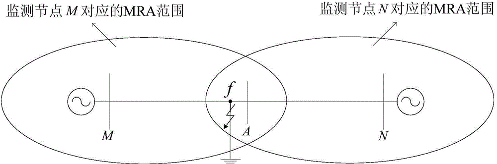
[0058] When a short-circuit fault occurs in a power grid component, the fault resistance exists widely and objectively, and its resistance value is affected by factors such as the type of short-circuit medium, the distance between phases, and the conductivity of the ground, and often presents strong random and uncertain characteristics. From the optimal configuration method of the traditional voltage sag monitoring node described in the background art, it can be seen that the assumption of the optimal configuration of the monitoring node based on the MRA principle is that the fault resistance value of the short-circuit fault point must be zero.

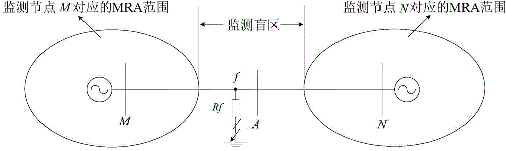
[0059] The fault resistance value has a significant impact on the voltage sag amplitude of the short-circuit fault point. The larger the fault resistance value is, the smaller the MRA range corresponding to each monitoring node is. If the monitoring node is configured in the whole network based on the optimal configuration method of th...


PUM


Abstract

The invention relates to an optimized configuration method of a voltage sag monitoring node. The method comprises: obtaining a critical fault resistor matrix based on a power grid topology and a system parameter; according to a fault resistor random distribution characteristic and the critical fault resistor matrix, establishing an inequality constraint; and obtaining an optimal monitoring node configuration scheme meeting the inequality constraint by targeting monitoring node number minimization. According to the method, a fault resistor of a short-circuit fault point is introduced into a monitoring node optimization configuration model, thereby eliminating a monitoring dead zone of the voltage sag.

Description

technical field [0001] The invention relates to the technical field of power distribution network planning, in particular to an optimal configuration method for voltage sag monitoring nodes. Background technique [0002] Voltage sag or drop refers to the phenomenon that the effective value of the supply voltage suddenly drops in a short period of time and then rises and recovers. In the power grid, the duration of this phenomenon is mostly 0.5 seconds to 1.5 seconds. The International Institute of Electrical and Electronics Engineers defines voltage sag as the rapid drop of the effective value of the supply voltage to 90% to 10% of the rated value, and then returns to around the normal value; while the International Electrotechnical Commission defines it as falling to 90% of the rated value % to 1% for a duration of 10 milliseconds to 1 minute. If the voltage sag lasts too long, the equipment will stop abnormally. With the continuous development of high-tech, a large numb...

Claims


Application Information

Patent Timeline
Patent Type & Authority Applications(China)
IPC IPC(8): G01R31/08
CPCG01R31/08
Inventor 陈礼频王海燕任志超曹开江胥威汀刘旭娜马瑞光汪伟陈谦张全明杜新伟
Owner STATE GRID SICHUAN ECONOMIC RES INST
Why Eureka
Try Eureka