Bridge crane conical motor

A technology of conical motors and motor shafts, which is applied to electrical components, electromechanical devices, electric components, etc., can solve the problems of high startup frequency, aggravated bearing wear, and short working cycle, so as to increase the average safe service life and improve safe use The effect of life and maintenance cost reduction

Inactive Publication Date: 2015-09-02
济南市平阴县玛钢厂
View PDF6 Cites 2 Cited by
  • Summary
  • Abstract
  • Description
  • Claims
  • Application Information

AI Technical Summary

Problems solved by technology

Compared with other motors, due to the different nature of the work, the conical motor used in the driving, first, due to the long working time, short working cycle and high starting frequency, the thrust spring will be distorted, deformed or twisted, resulting in a large braking gap. In case of timely adjustment or brake failure, use failure occurs. If the spring breaks, the motor brake failure will also cause the driving cone motor to burn out in a very short period of time; The sleeve will increase the wear of the bearing, causing the rotor to sink or the deflection of the crankshaft to make the rotor eccentric, causing the motor temperature to be too high. The movement causes the bearing to displace, resulting in sweeping and burning the driving cone motor; therefore, it has a great impact on the safe service life of the driving cone motor

Method used


Image

  • Bridge crane conical motor

Examples


Embodiment 1

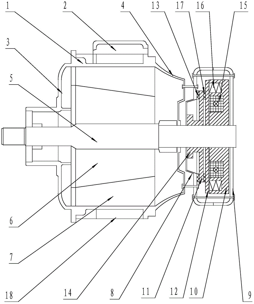
[0015] Such as figure 1 As shown, a driving cone motor includes a housing 1, a front end cover 3, and a rear end cover 4. A junction box 2 is arranged on the outer wall of the housing 1, and the front end cover 3 is arranged on the left end of the housing 1, so that The rear end cover 4 is arranged on the right end of the housing 1, and is characterized in that it also includes a motor shaft 5, on which a conical rotor 6 is arranged, and the outer ring of the conical rotor 6 is provided with a The rotor 6 is matched with the stator 7, and the motor shaft 5 is rotationally connected with the front end cover 3 and the rear end cover 4 using bearings respectively; the motor shaft 5 also has a part extending from the rear end cover 4, and the motor shaft 5 extends The driving cone motor braking device is installed on the part of the rear end cover 4;

[0016] The driving cone motor braking device is a driving cone motor brake, and the driving cone motor brake includes a front bra...

Embodiment 2

[0018] Such as figure 1 As shown, a driving cone motor includes a housing 1, a front end cover 3, and a rear end cover 4. A junction box 2 is arranged on the outer wall of the housing 1, and the front end cover 3 is arranged on the left end of the housing 1, so that The rear end cover 4 is arranged on the right end of the housing 1, and is characterized in that it also includes a motor shaft 5, on which a conical rotor 6 is arranged, and the outer ring of the conical rotor 6 is provided with a The rotor 6 is matched with the stator 7, and the motor shaft 5 is rotationally connected with the front end cover 3 and the rear end cover 4 using bearings respectively; the motor shaft 5 also has a part extending from the rear end cover 4, and the motor shaft 5 extends The driving cone motor braking device is installed on the part of the rear end cover 4;

[0019] The driving cone motor braking device is a driving cone motor brake, and the driving cone motor brake includes a front bra...


PUM


Abstract

The invention discloses a bridge crane conical motor, comprising a housing, a front end cover, and a rear end cover. The motor also comprises a motor shaft. The motor shaft is provided with a conical rotor. The outer ring of the conical rotor is provided with a stator matched with the conical rotor. The motor shaft is rotatably connected with the front end cover and the rear end cover respectively using bearings. The motor shaft is also provided with a part extending out of the rear end cover. The part of the motor shaft, extending out of the rear end cover, is provided with a bridge crane conical motor braking device. Since the part of the motor shaft of the bridge crane conical motor, extending out of the rear end cover, is provided with the bridge crane conical motor braking device, and a technical problem that an original bridge crane conical motor is prone to have friction between the rotor and the stator to burn the bridge crane conical motor is overcome. The bridge crane conical motor realizes to operate safely and stably, operation and maintenance cost of the bridge crane conical motor is reduced, and safe service life of the bridge crane conical motor is improved.

Description

technical field [0001] The invention belongs to the technical field of hoisting machinery, in particular to a driving cone motor. Background technique [0002] In hoisting machinery, motors are already essential driving equipment. At present, conical motors are mostly used in hoisting machinery, and the conical motors mainly include a shell, a motor shaft, a conical rotor set on the motor shaft, a stator matched with the conical rotor set on the outer ring of the conical rotor, and a set at one end of the motor shaft. The fan brake wheel, the friction plate set on the outer ring of the fan brake wheel, the thrust spring, the support sleeve, and the thrust bearing; the start and brake of the cone motor are installed on the fan of the cone motor. In the state, the friction plate on the fan is tightly combined with the friction surface on the end cover by a thrust spring, so that the conical motor is in the brake stop state; when the conical motor is energized and working, the...

Claims


Application Information

Patent Timeline
Patent Type & Authority Applications(China)
IPC IPC(8): H02K7/102H02K5/16
Inventor 董宜胜赵学增刘德军
Owner 济南市平阴县玛钢厂
Why Eureka
Try Eureka