Check patentability & draft patents in minutes with Patsnap Eureka AI!

Electronic unit

A technology for electronic units and circuit boards, applied to electrical components, electrical equipment casings/cabinets/drawers, casings/cabinets/drawer components, etc., can solve problems such as connector damage, restricted assembly direction, and design restrictions

Inactive Publication Date: 2015-09-02
TOYOTA IND CORP
View PDF3 Cites 0 Cited by
  • Summary
  • Abstract
  • Description
  • Claims
  • Application Information

AI Technical Summary

Problems solved by technology

In particular, the housing 72 used as a part of the electronic unit 70 restricts the direction of assembly, thereby placing restrictions on the design of the electronic unit 70
In the electronic unit 60 and the electronic unit of the above-mentioned publication, the connector is directly mounted to the housing, and the vibration transmitted to the housing is directly transmitted to the connector, thereby possibly causing damage to the connector.
Also, since the housing and connector have different coefficients of thermal expansion, the connector may be damaged by the heat transferred to the housing

Method used


Image

  • Electronic unit
  • Electronic unit
  • Electronic unit

Examples


Embodiment Construction

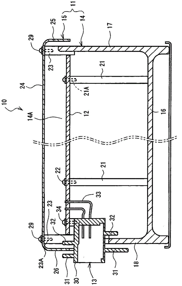
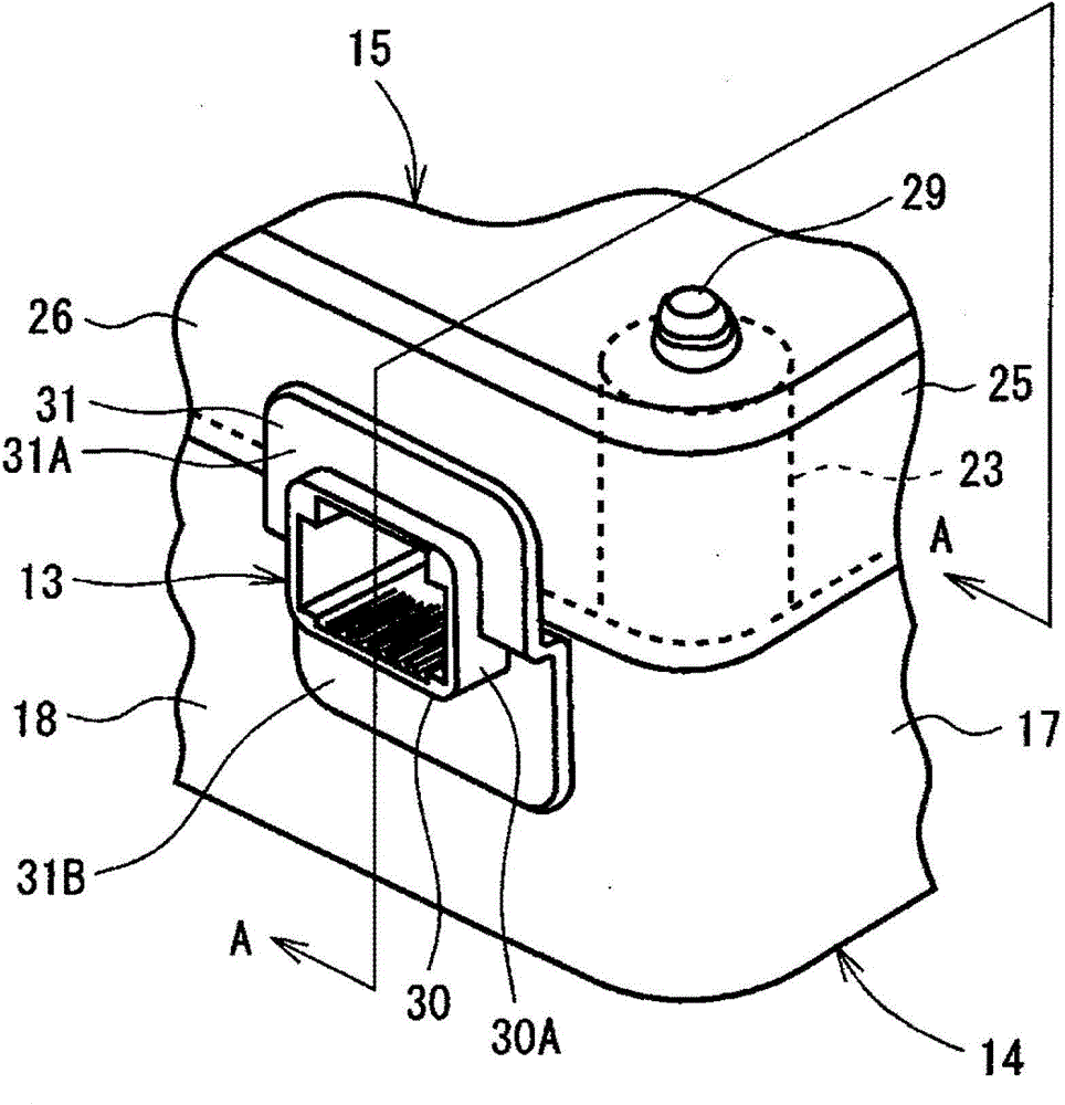
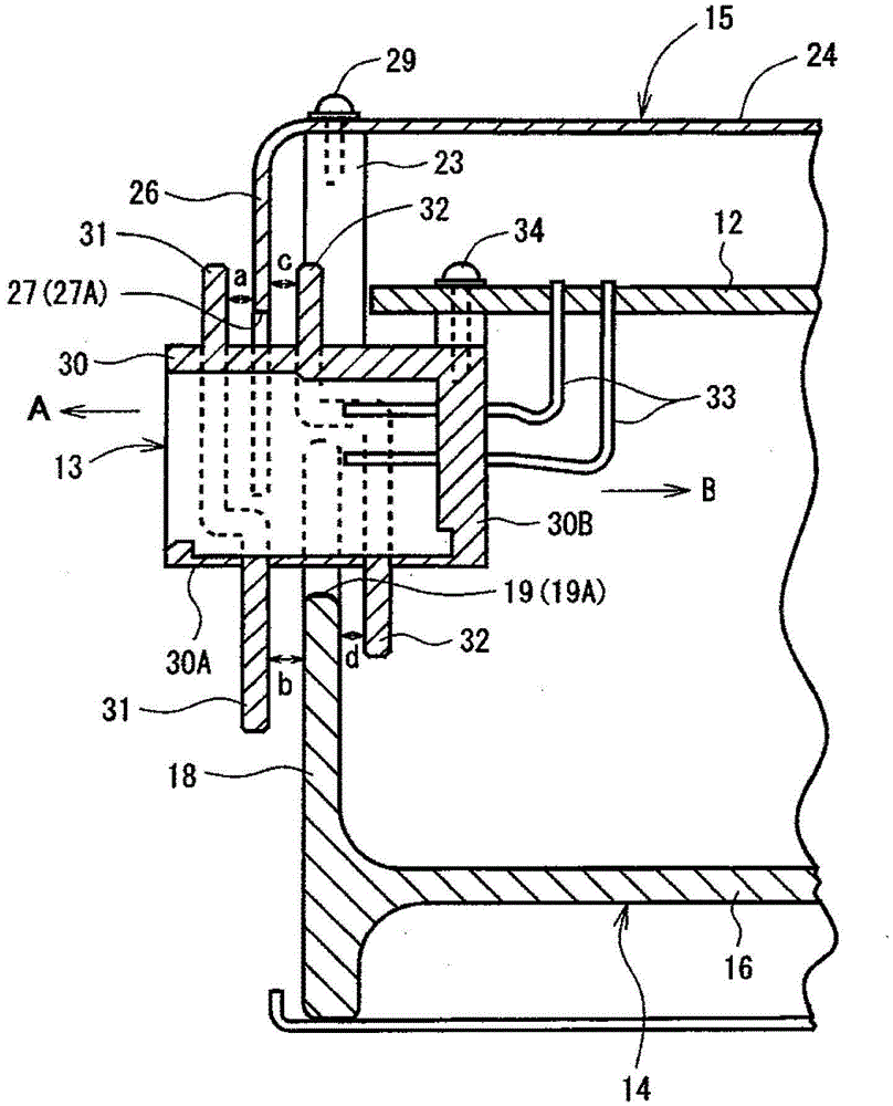
[0020] The following will refer to figure 1 to FIG. 6 describe an electronic unit according to an embodiment of the present invention. refer to figure 1 , the electronic unit marked by reference numeral 10 includes a housing 11, a circuit board 12 and a connector 13, wherein the circuit board 12 is accommodated in the housing 11, the connector 13 is installed on the circuit board 12 and the connection A part of the device 13 is exposed outside the case 11. The case 11 includes a box-shaped case member 14 having an opening 14A and a cover 15 that closes the opening 14A of the case member 14 .

[0021] The case member 14 of the case 11 is formed in a box shape having an opening 14A. The housing member 14 includes a substantially rectangular-shaped bottom 16 and side walls 17 , 18 extending vertically from four sides of the rectangular bottom 16 , respectively. The case member 14 is formed by aluminum die casting, press working, or resin molding. A plurality of support mem...


PUM


Abstract

An electronic unit includes a circuit board, a connector and a housing. The connector is electrically connected to the circuit board through a lead wire. The housing accommodates therein the circuit board having an opening through which a part of the connector is exposed outside the housing, and a clearance is formed between an edge portion of the opening of the housing and the connector. The electronic unit further includes an outer rib, an inner rib and a projection. The inner rib is formed on the inner side of the housing than the outer rib. The projection is inserted between the outer rib and the inner rib.

Description

technical field [0001] The present invention relates to electronic units, and more particularly to an electronic unit provided with a housing in which a circuit board is accommodated and a connector having leads electrically connecting the connector to the circuit board . Background technique [0002] An electronic unit provided with a connector mounted on a printed circuit board arranged in a housing has a structure that prevents wires from entering the housing to prevent electric shock. in such as Figure 8 In a conventional electronic unit 50 shown in , a connector 53 is connected to one end of a wire harness 52 , and the other end of the wire harness 52 is connected to a circuit board (not shown) disposed in a housing 51 of the electronic unit 50 . The wire harness 52 has therein a plurality of electric wires each connected to a circuit board, and the housing 51 has therein a grommet 54 through which a plurality of holes are formed and through which the electric wires a...

Claims


Application Information

Patent Timeline
IPC IPC(8): H05K5/02H01R13/46
CPCH05K5/0069
Inventor 村田达哉
Owner TOYOTA IND CORP
Features
  • R&D
  • Intellectual Property
  • Life Sciences
  • Materials
  • Tech Scout
  • Unparalleled Data Quality
  • Higher Quality Content
  • 60% Fewer Hallucinations
Learn More