Portable breathing machine

A ventilator and portable technology, applied in the field of ventilators, can solve the problems of increased cost, increased volume, and difficulty in implementation, and achieve the effect of improving the degree of noise reduction

Inactive Publication Date: 2015-09-09
HUNAN MICOME ZHONGJIN MEDICAL SCI & TECH DEV CO LTD
View PDF5 Cites 4 Cited by
  • Summary
  • Abstract
  • Description
  • Claims
  • Application Information

AI Technical Summary

Problems solved by technology

[0004] In the prior art, there are mainly three types of control for fan noise: 1. Wrap the fan in a thick box with sound-proof material, usually EVA material, but this requires higher sound-proof material, and the volume of the box generally requires Large size is not conducive to cost control and volume control of the ventilator. Because home ventilators are mainly used in homes and sleep centers, they are generally not made too large for convenience.
2. Create a soundproof environment through the gas path structure. This method is low in cost, but it has extremely high structural requirements and is generally difficult to achieve
3. Increase the number of rigid connection parts to fix the fan by adding special protection treatment, reduce the vibration of the fan and reduce the noise, but this solution also has the problems of increased volume and increased cost
The air blown out by the fan is not a stable airflow, and usually has a large disturbance. If the airflow blown by the fan is directly collected, the obtained data will not be stable, which will have a great impact on the algorithms in the software. At the same time, it will also make the patient feel unwell

Method used


Image

  • Portable breathing machine
  • Portable breathing machine
  • Portable breathing machine

Examples


Embodiment Construction

[0067] The following examples are used to illustrate the present invention, but are not intended to limit the scope of the present invention.

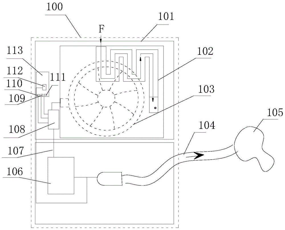
[0068] Such as figure 1 As shown, the low-noise ventilator of the present invention includes a housing 100, the housing is provided with an air inlet, and the housing is provided with a fan box 101, an intercepting device 108, a humidifying device 106 and a control device 113, and the fan 8 passes through the noise reduction device Installed in the fan box 101, the air outlet of the fan box 101 is connected to the internal breathing pipe 107, and the internal breathing pipe 107 is provided with a shut-off device 108, the flow sensor 109, the pressure sensor 110 and the flow rate sensor 111 are arranged in the described shut-off device 108, The flow sensor 109, the pressure sensor 110 and the flow rate sensor 111 are all connected to the control device, and the air outlet of the intercepting device 108 is connected to the humidifier 10...


PUM


Abstract

A portable breathing machine comprises a shell. A fan box (101), cut-off equipment (108) and a control device (113) are arranged in the shell. A fan (8) is arranged in the fan box (101) through a noise reduction device. An air outlet of the fan is in air connection with an internal breathing pipe (107). The cut-off equipment (108) is arranged on the internal breathing pipe (107). An air outlet of the cut-off equipment (108) is connected with a breathing pipe (104) and a mask (105). The noise reduction device comprises a lower flexible cover (3) and an upper flexible cover (5). The lower flexible cover (3) and the upper flexible cover (5) are matched to form a sealed cavity for containing the fan (8). The fan (8) is suspended on the upper flexible cover (5) through a flexible suspension column (6). An S-shaped sealed air channel (3-1) and a fan air inlet channel (3-2) which are connected in sequence are integrally formed on the noise reduction device. The integrally-formed noise reduction device and the air channel structure act together so that the work noise of the breathing machine can be lower than 15 decibels. Breathing air parameters can be detected conveniently and accurately, and 360-degree backflow prevention can be achieved.

Description

technical field [0001] The invention relates to the field of ventilators, in particular to a portable ventilator. Background technique [0002] Home sleep ventilators are mainly used in individual families, sleep centers and small clinics, mainly for patients with apnea syndrome. The ventilator relies on the fan to pressurize the gas in the pipeline. During the working process, the fan will inevitably make noise. Because the patient's tolerance threshold for sound is lowered, and the single and repeated stimulation of these sounds to the patient makes the patient unable to distinguish between Day and night, so the adverse stimulation of the ventilator noise to the patient is great. How to control the noise to a minimum and not affect the sleep of patients is a major issue that every ventilator manufacturer must face. [0003] Fan noise is mainly divided into two types, one is the whistling sound caused by the rapid rotation of the fan and the friction between the blades an...

Claims


Application Information

Patent Timeline
IPC IPC(8): A61M16/00
Inventor 戴征杨贯中丁锦刘炜徐勤鹏黄皓轩李伟利何超雷孟航
Owner HUNAN MICOME ZHONGJIN MEDICAL SCI & TECH DEV CO LTD
Why Eureka
Try Eureka