
A flow regulating mechanism

A technology of flow adjustment and flow adjustment plate, which is applied in the field of flow adjustment mechanism for feed control of roller presses, can solve problems such as roll surface impact, roll surface fatigue damage, etc., to reduce material column collapse, prolong service life, reduce The effect of small shocks

Active Publication Date: 2017-06-30
CHENGDU LEEJUN TECH CO LTD
View PDF6 Cites 0 Cited by
  • Summary
  • Abstract
  • Description
  • Claims
  • Application Information

AI Technical Summary

Problems solved by technology

This will cause the slump to have a greater impact on the roll surface, resulting in fatigue damage to the roll surface

Method used


Image

  • A flow regulating mechanism
  • A flow regulating mechanism
  • A flow regulating mechanism

Examples


Embodiment Construction

[0017] The present invention will be further described below in combination with specific embodiments and accompanying drawings.

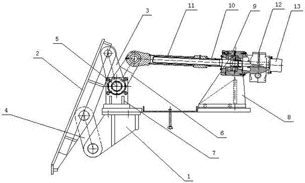
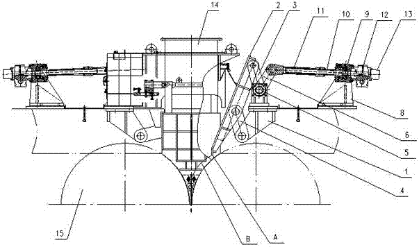
[0018] Such as Figure 2 to Figure 4 As shown, a flow regulating mechanism includes a bracket 1, a flow regulating plate 2, a first connecting rod 3, a second connecting rod 4, a rotating shaft 5, a transmission rod 6 and a driving mechanism, and the rotating shaft 5 passes through a support 7 Installed on the bracket 1, one end of the first connecting rod 3 is fixedly connected to the rotating shaft 5, the other end is hinged to the top of the flow regulating plate 2, one end of the second connecting rod 4 is hinged to the bracket 1, and the other end is connected to the flow regulating plate 2 Lower center hinged. One end of the transmission rod 6 is fixedly connected to the rotating shaft 5, and the other end is hinged to the output end of the driving mechanism, and an included angle of 30°-60° is formed between the transmission rod 6 and the f...


PUM


Abstract

The invention discloses a flow regulation mechanism which comprises a bracket, a flow regulation plate, a first side link, a second side link, a rotating shaft and a driving mechanism, wherein the rotating shaft is mounted on the bracket via a support; the driving mechanism drives the rotating shaft to rotate; one end of the first side link is fixedly connected with the rotating shaft; the other end of the first side link is articulated with the top end of the flow regulation plate; one end of the second side link is articulated with the bracket; and the other end of the second side link is articulated with the middle lower part of the flow regulation plate. The flow regulation mechanism has the benefits that a material collapse phenomenon of a stock column can be greatly reduced, and the impact of materials on a roller surface is reduced when the flow regulation mechanism is used in a roller press, so that the service life of the roller surface is prolonged.

Description

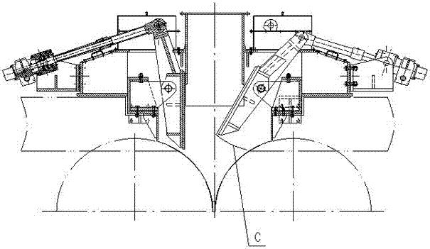
technical field [0001] The invention relates to a flow regulating mechanism, in particular to a flow regulating mechanism used for the feed control of a roller press. Background technique [0002] As a kind of grinding equipment, the roller press is widely used in the grinding system of cement raw meal and clinker because of its energy-saving and high-efficiency advantages. In recent years, it has been gradually applied to the ore grinding system. However, because the roller surface is easily damaged and the maintenance cost is high, the promotion of the roller press in the field of ore grinding is limited. One of the main reasons for the damage of the roller surface is that when the traditional flap feeding device adjusts the flow rate, it is easy to cause the material column to collapse. The movement trajectory of the lower end point of the flow regulating plate when regulating the flow is as follows: figure 1 Curve C, when the opening of the flow regulating plate is the...

Claims


Application Information

Patent Timeline
Patent Type & Authority Patents(China)
IPC IPC(8): B02C4/28B02C23/02
CPCB02C4/286
Inventor 何亚民魏勇徐智平
Owner CHENGDU LEEJUN TECH CO LTD
Learn More