Roller blind system for a sliding roof

A technology of roller blinds and rollers, which is applied in the field of roller blind systems and can solve problems such as increased space requirements and high manufacturing costs

Inactive Publication Date: 2015-09-09
ROOF SYST GERMANY
View PDF1 Cites 1 Cited by
  • Summary
  • Abstract
  • Description
  • Claims
  • Application Information

AI Technical Summary

Problems solved by technology

In this known roller blind system, disadvantages have been found to be an increased space requirement and higher manufacturing costs due to the compensating spring

Method used


Image

  • Roller blind system for a sliding roof
  • Roller blind system for a sliding roof
  • Roller blind system for a sliding roof

Examples


Embodiment Construction

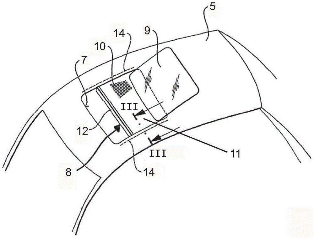
[0041] figure 1Shown is a roof 5 provided with an opening 7 and a roller blind system. The cover 9 of the sliding roof system is joined to the opening 7 . The cover 9 can be in its shaded position closing the opening 7 and is shown in figure 1 Move between the light-transmitting positions in . Below the cover 9 and below the opening 7 there is a roller blind 10 which is part of a roller blind system 8 . The roller blind 10 can move forward and backward based on the vehicle. When the roller blind 10 is fully pushed back, the opening 7 is fully exposed. Fresh air and sunlight can freely enter the car interior space. The opening 7 is covered by the roller blind 10 when the roller blind 10 is fully advanced. Fresh air and sunlight can thus only enter the vehicle interior to a limited extent.

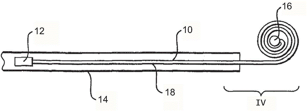
[0042] The roller blind 10 comprises a roller blind fabric 11 of flexible material such as cloth or plastic film. The front end of the roller shade fabric is provided with a transver...


PUM


Abstract

A roller blind system for a sliding roof with at least one guide rail and with a roller blind with a roller blind fabric mounted on at least one guiding strip is provided, The guiding strip is sectionally guided in the guide rail and its end that is located outside the guide rail contracts to form a coil during a movement of the roller blind in opening direction, wherein at least one device for increasing the opening force of the roller blind is provided, which is designed and arranged such that the device produces an additional force at least in opening direction.

Description

technical field [0001] The invention relates to a roller blind system for sliding roofs, which has at least one guide rail and has a roller blind comprising a roller blind fabric mounted on at least one guide strip, wherein the guide strip is partially guided in the guide rail and placed on the roller blind. During the movement in the light transmission direction, the end of the guide strip outside the guide rail is contracted to form a roll. Background technique [0002] EP1900560A1 discloses such a roller blind system. The advantage of such a roller blind system is that it is very compact. The guide strip, designed as a spring steel strip, serves both to fasten the roller blind and as a return spring. However, it has been found that the operating force required to move the roller blind in the guide rail changes depending on the direction of movement. When the roller blind is moved to a more shaded position, ie pulled out, more operating force is required than to push ba...

Claims


Application Information

Patent Timeline
Patent Type & Authority Applications(China)
IPC IPC(8): B60J7/02B60J3/02B60J7/057E06B9/56
CPCB60J7/067B60J7/0015
Inventor J·罗德尔P·里格尔R·阿诺德S·康凯尔K·杜德尔D·施魏诺赫
Owner ROOF SYST GERMANY
Why Eureka
Try Eureka