
Vehicle Mobility Booster

A technology of vehicle movement and booster, which is applied in vehicle maintenance, vehicle control devices, shunting equipment, etc.

Active Publication Date: 2016-08-24
HUBEI REMOTE RAILWAY TECH
View PDF6 Cites 0 Cited by
  • Summary
  • Abstract
  • Description
  • Claims
  • Application Information

AI Technical Summary

Problems solved by technology

The existing common method is to manually assist the crowbar to push the vehicle first, and then use multiple manpower to move the vehicle. Generally, one vehicle requires 4 to 5 people, and two vehicles require 8 to 10 people. However, when the number of vehicles is large, such as When it is increased to four or five vehicles, it is difficult to push by manpower, so the method of manually moving the vehicle is clumsy, laborious and difficult to move the vehicle. Therefore, there is an urgent need for a vehicle booster that is easy to use and labor-saving moving vehicle
[0003] This shows that above-mentioned existing vehicle mobile method obviously still has inconvenience and defect in use, and demands urgently further improving
In order to solve the above-mentioned problems, the relevant manufacturers have tried their best to find a solution, but for a long time no suitable design has been developed, and the general product has no suitable structure to solve the above-mentioned problems. This is obviously the relevant industry. Urgent problem

Method used


Image

  • Vehicle Mobility Booster
  • Vehicle Mobility Booster
  • Vehicle Mobility Booster

Examples


Embodiment Construction

[0034] In order to further explain the technical means and effects of the present invention to achieve the intended purpose of the invention, the specific implementation, structure and characteristics of a vehicle moving booster proposed according to the present invention will be described below in conjunction with the accompanying drawings and preferred embodiments. And its effect, detailed description is as follows.

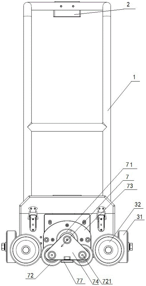
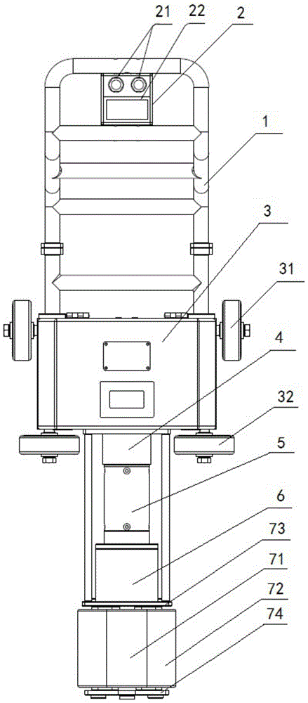
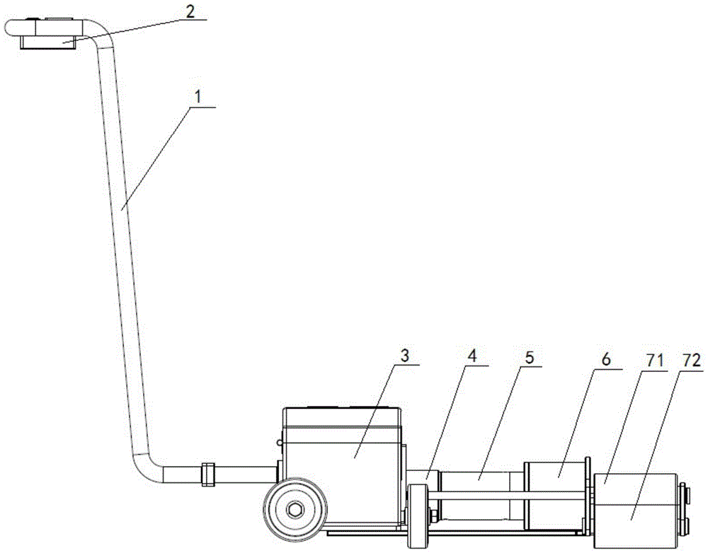
[0035] see Figure 1 to Figure 3 , which are the front view, the top view and the left view of the present invention, respectively, a vehicle moving booster of the present invention, comprising: a control handle 1, a power module 3, a DC motor 4, a reducer 5, and a coupling 6 connected in sequence And transmission mechanism 7.

[0036] The control handle 1 is configured as a detachable structure. Specifically, it can be connected with the power module 3 through a connection form such as screws, so as to facilitate disassembly. The control handle 1 is also pro...


PUM


Abstract

The invention relates a vehicle mobile booster. The vehicle mobile booster comprises a control hand shank, a power supply module, a direct-current motor, a decelerator, a coupler and a transmission mechanism which are sequentially connected, wherein the transmission mechanism comprises a driving wheel, driven wheels, a front connecting plate and a rear connecting plate, the driving wheel and the driven wheels are arranged at one end of the coupler, the driving wheels drives the driven wheels to rotate, a round hole and oval holes are respectively formed in the front connecting plate and the rear connecting plate, both ends of the central shaft of the driving wheel are respectively arranged in the round holes of the front connecting plate and the rear connecting plate, and both ends of the central shaft of each driven wheel are respectively arranged in the oval holes in the front connecting plate and the rear connecting plate. The vehicle mobile booster disclosed by the invention is simple in structure, low in cost and convenient to operate; the vehicle booster can automatically regulate a distance between the driving wheel and each driven wheel, and the transmission effect is good.

Description

technical field [0001] The invention relates to a shunting device, in particular to a booster for helping the vehicle move. Background technique [0002] In the maintenance process of rail vehicles, the vehicle is often at a certain distance from the maintenance point, so it is necessary to move the vehicle to a suitable location for maintenance. The existing common method is to manually assist the crowbar to push the vehicle first, and then use multiple manpower to move the vehicle. Generally, one vehicle requires 4 to 5 people, and two vehicles require 8 to 10 people. However, when the number of vehicles is large, such as When it is increased to four or five vehicles, it is difficult to push by manpower, so the method of manually moving the vehicle is clumsy, laborious and difficult to move the vehicle. Therefore, there is an urgent need for a vehicle booster that is easy to use and labor-saving moving vehicle. [0003] This shows that above-mentioned existing vehicle mo...

Claims


Application Information

Patent Timeline
Patent Type & Authority Patents(China)
IPC IPC(8): B60S13/00
CPCB60S13/00
Inventor 胡明星张永贵赵登华赵卫健
Owner HUBEI REMOTE RAILWAY TECH
Learn More