Automatic control type cable uncoiling device

A driving device and cable technology, used in transportation and packaging, transportation of filamentous materials, and thin material handling, etc., can solve problems such as cable damage, large cable tension, and large rolling friction between cable reels and crossbars. The effect of transportation and protection from damage

Active Publication Date: 2015-09-09
CHANGLAN CABLE ACCESSORIES
View PDF11 Cites 11 Cited by
  • Summary
  • Abstract
  • Description
  • Claims
  • Application Information

AI Technical Summary

Problems solved by technology

The cable reel is only supported by the cross bar between the elevators. When the tractor and conveyor pull the cable to drive the cable reel, there is rolling friction between the cable reel and the cross bar. Even if it is rolling friction, the total weight of the cab

Method used


Image

  • Automatic control type cable uncoiling device
  • Automatic control type cable uncoiling device
  • Automatic control type cable uncoiling device

Examples


Embodiment Construction

[0024] The present invention will be further described below in conjunction with accompanying drawing.

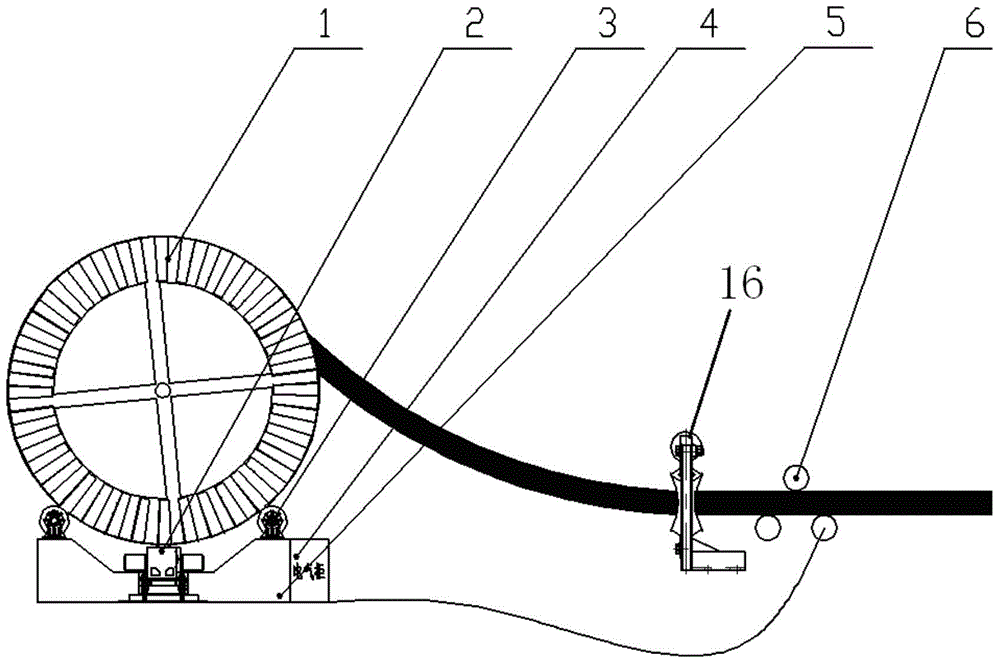
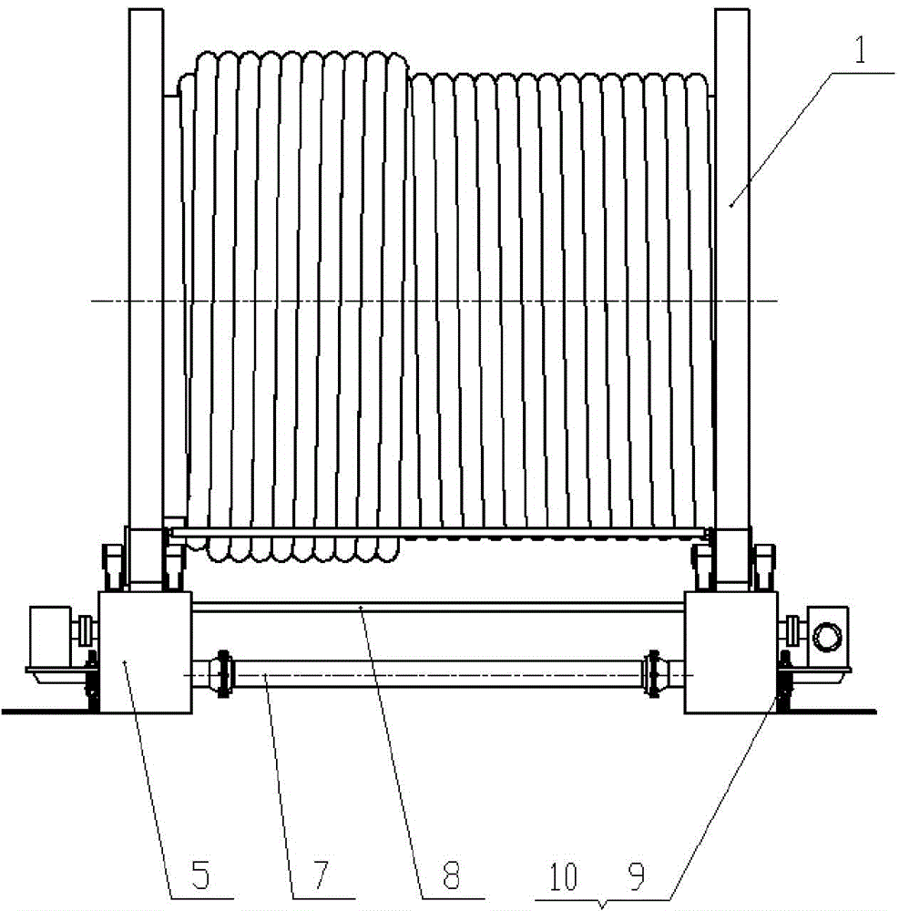
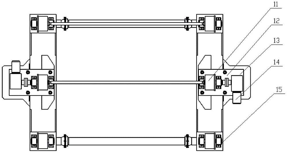
[0025] see figure 1 , figure 2 , image 3 , Figure 4 with Figure 5 , the automatic control device for cable deployment, including two underframes 5, the two ends of each underframe 5 are provided with support wheels 3 through brackets 15, and the middle part is provided with a cable reel driving device 2, and the rim of the cable reel 1 can be connected with the support The wheel 3 and the cable reel driving device 2 are contacted and driven; a tension measuring device 6 is also included, and a control system 4 is communicatively connected with the tension measuring device 6 and the cable reel driving device 2 .

[0026] Further, the two underframes 5 are connected in a flexible way by connecting beams 7 in a ball connection. The connection mode between the connecting beam and the flexible ball of the chassis is conducive to placing the equipment on uneven ground. ...


PUM


Abstract

The invention discloses an automatic control type cable uncoiling device. The device comprises two bottom frames (5); supporting wheels (3) are arranged at two ends of each bottom frame (5); a cable plate driving device (2) is arranged in the middle of each bottom frame (5); the wheel edge of a cable plate is in frictional transmission with each supporting wheel (3) and the cable plate driving device (2). The device further comprises a tension measuring device (6) and a control system (4), wherein the control system (4) is in communication connection with the cable plate driving device (2) through the tension measuring device (6). According to the device, the cable plate is driven through frictional force; the flexible adjustable driving device and the bottom frame splicing structure enable the device to be adapted to the cable plate with different diameter and width; the tension measuring device and the control system achieve synchronous starting, stopping and conveying speed of front and rear end cable conveying devices.

Description

technical field [0001] The invention relates to a cable deployment device, in particular to an automatically controlled cable deployment device. Background technique [0002] At present, the domestic laying of high-voltage cables basically uses a tractor to pull the cable out of the cable reel. After the cable reaches the conveyor, the conveyor provides the conveying force, and the tractor also provides part of the traction force at this time, and then pulls the cable to drive the cable reel to rotate. purpose of expansion. The cable reel is only supported by the cross bar between the elevators. When the tractor and conveyor pull the cable to drive the cable reel, the cable reel and the cross bar will have rolling friction. Even if it is rolling friction, due to the total The weight is generally large, and the rolling friction between the cable reel and the cross bar will be relatively large, so the tension on the cable is relatively large, which will easily cause damage to...

Claims


Application Information

Patent Timeline
IPC IPC(8): B65H49/18
CPCY02P70/10
Inventor 李绍斌叶波王威
Owner CHANGLAN CABLE ACCESSORIES
Why Eureka
Try Eureka