
Internal transportation machinery flow division device

A shunt device and mechanical technology, which is applied in the field of lubrication adjustment system in the technical field of mechanical design, can solve the problem that the oil pressure cannot be continuously adjusted, and achieve the effect of simple structure and reasonable design.

Inactive Publication Date: 2015-09-09
高雅
View PDF1 Cites 2 Cited by
  • Summary
  • Abstract
  • Description
  • Claims
  • Application Information

AI Technical Summary

Problems solved by technology

[0003] After searching the prior art documents, it was found that Chinese patent application number 201110044577.9, patent name: engine oil pressure control device, this patented technology provides a kind of engine oil pressure regulating device, which can better realize the regulation of engine oil pressure; The pressure adjustment is staged, and the continuous adjustment of the oil pressure cannot be realized

Method used


Image

  • Internal transportation machinery flow division device
  • Internal transportation machinery flow division device
  • Internal transportation machinery flow division device

Examples


Embodiment

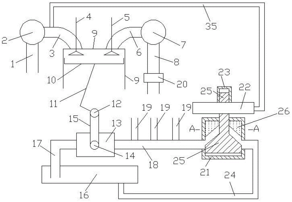
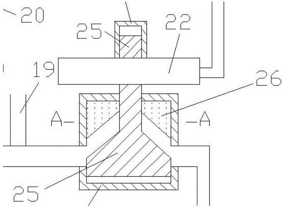
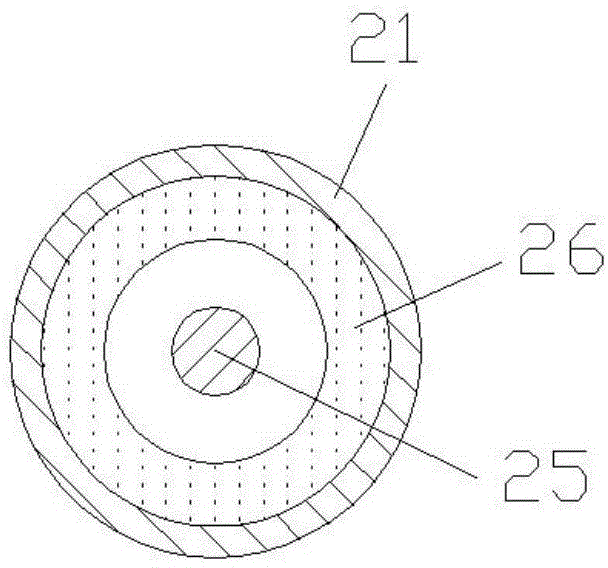
[0017] Such as Figure 1 to Figure 6 As shown, the present invention comprises compressor intake pipe 1, compressor 2, engine intake pipe 3, intake valve 4, exhaust valve 5, engine exhaust pipe 6, turbine 7, turbine outlet pipe 8, cylinder 9, piston 10 , connecting rod 11, crankshaft 12, oil pump 13, oil pump gear 14, chain 15, oil pan 16, oil suction pipe 17, main oil passage 18, oil distribution passage 19, catalytic package 20, first control chamber 21, second Two control cavity 22, nut 23, oil return pipe 24, valve body 25, filling body 26, fixed body 27, first through pipe 28, second through pipe 29, spring 30, rotating block 31, rotating plate 32, connecting plate 33. The rotating shaft 34, the connecting pipe 35, the air inlet and outlet of the compressor 2 are respectively connected with the air outlet of the compressor inlet pipe 1 and the air inlet of the engine air inlet pipe 3, and the air outlet of the engine air inlet pipe 3 is connected with the engine air inlet...


PUM


Abstract

The invention relates to the mechanical design technical field, particularly to an internal transportation machinery flow division device. The internal transportation machinery flow division device comprises control chambers, a valve body, a filling body, a fixing body, penetrating pipes, a spring, a rotating block, a rotating plate, a connecting plate, a rotating shaft and a connecting pipe; the lower section of the valve body is in a conical shape; the middle section of the valve body is provided with four ribs; the upper section of the valve body is provided with external threads; the first penetrating pipe and he second penetrating pipe are arranged on the fixing body; the area of the cross section of the first penetrating pipe is smaller than that of the cross section of the second penetrating pipe; one end of the connecting pipe is communicated with an internal chamber body of the second control chamber; the other end of the connecting pipe is communicated with an intake pipe of an engine. When the pressure in the intake pipe of the engine is high, the valve body moves upward, a main oil channel and an oil return pipe are partitioned, and the pressure of the engine oil of the main oil channel is increased. When the pressure in the intake pipe of the engine is low, the valve body moves downward, the main oil channel is communicated with the oil return pipe, and the pressure of the engine oil of the main oil channel is reduced. The internal transportation machinery flow division device is reasonable in design, simple in structure and suitable for the optimized design of mechanical lubrication systems.

Description

technical field [0001] The invention relates to a lubricating adjustment system in the technical field of mechanical design, in particular to an internal shunting device for traffic machinery suitable for supercharged engines. Background technique [0002] When the engine is working, the speed is very high, and the parts between the piston and the cylinder wall, between the connecting rod bearing bush and the crankshaft are tightly matched. If these matching parts are not fully lubricated, dry friction will occur. The heat generated by dry friction in a short period of time is enough to melt the metal, causing damage or even jamming of the parts (piston scuffing, crankshaft pads, etc.), so the matching parts in the engine must be well lubricated. When the lubricating oil flows to the mating part, an oil film will be formed on the friction surface. In order to ensure that the lubricating oil can reach the mating surface smoothly, the engine lubricating oil must have a certai...

Claims


Application Information

Patent Timeline
Patent Type & Authority Applications(China)
IPC IPC(8): F01M1/16
Inventor 高雅王娴
Owner 高雅
Learn More