
Scalable gear fatigue testbed and stress cycle number calculation method thereof

A technology of fatigue test and scalability, applied in the field of gears, can solve the problems of unsuitable for large gear fatigue test, fixed span or small adjustment range, unsuitable for gear fatigue test, etc., to achieve simple and convenient measurement and calculation, high rotation speed The effect of wide range and fast test speed

Active Publication Date: 2015-09-09
黄山市开发投资集团有限公司
View PDF8 Cites 3 Cited by
  • Summary
  • Abstract
  • Description
  • Claims
  • Application Information

AI Technical Summary

Problems solved by technology

The existing gear fatigue test fixture generally includes a loading part and a gear installation part, wherein the loading part includes two loading heads. For example, Chinese patent document CN201096617 discloses a gear bending fatigue universal test fixture. During the test, two loading heads The head should be added to the two teeth on both sides of the gear axis at the same time. It is difficult to ensure that the distance between the force point of the two teeth and the central axis of the gear is the same during operation, so it is easy to cause uneven loading on the left and right teeth. Moreover, during the test, the loads on the two gear teeth tend to change each other, resulting in inaccurate test data; in addition, the span of the two loading heads is fixed or the adjustment range is small, which is not suitable for fatigue tests of various types of gears, especially It is suitable for the fatigue test of large gears; if it is equipped with fixtures of various sizes and specifications, the cost of the fixtures will be relatively high

Method used


Image

  • Scalable gear fatigue testbed and stress cycle number calculation method thereof
  • Scalable gear fatigue testbed and stress cycle number calculation method thereof
  • Scalable gear fatigue testbed and stress cycle number calculation method thereof

Examples


Embodiment Construction

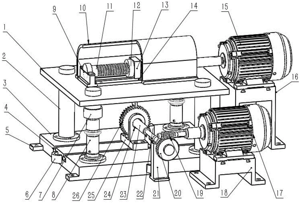
[0032] Such as figure 1 As shown, a scalable gear fatigue test bench includes: a loading part, a gear installation part and an upper top plate telescopic part;

[0033] The loading part includes an upper top plate 1, a screw base 9, a dust cover 10, a screw 11, a nut 12, a V-shaped block test thimble 13, a guide rail 14, a loading motor 15 and a loading motor base 16;

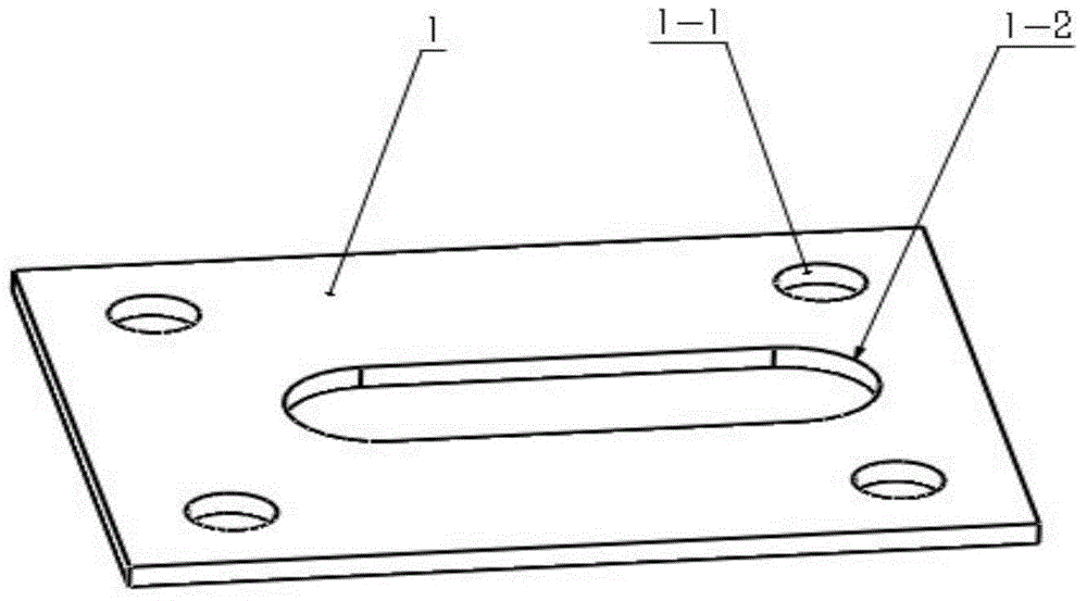
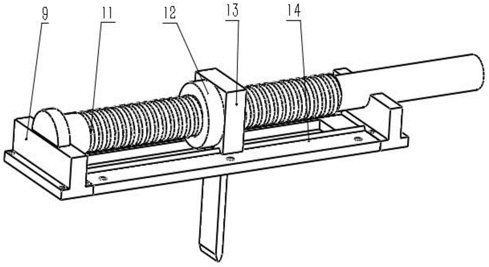
[0034] A guide rail 14 is provided on the upper top plate 1, and a lead screw base 9 is provided at both ends of the guide rail 14. In the lead screw base 9, a lead screw 11 is arranged above the guide rail 14, and is driven by a loading motor 15. The screw 11 is equipped with a nut 12 and a V-shaped block test thimble 13 on the nut 12; the material used for the V-shaped block test thimble 13 is hard alloy steel material, which has high hardness, wear resistance and impact resistance; the loading part The ball screw mechanism drives the screw 11 to rotate through the loading motor 15, the loading motor 15 is f...


PUM


Abstract

The invention relates to a scalable gear fatigue testbed and a stress cycle number calculation method. The scalable gear fatigue testbed is characterized in that the testbed consists of a loading part, a gear mounting part and an upper top plate telescoping part; a loading motor drives a lead screw to rotate, thereby driving a nut and a V-shaped block test thimble to move along a guide rail horizontally in a reciprocating manner; a thimble head of the V-shaped block test thimble generates radial force on to-be-tested gear teeth of a test gear, thereby compelling the to-be-tested gear teeth to break; and then a gear rotating motor is used to drive a worm and a worm wheel to rotate, thereby driving the test gear to rotate to new to-be-tested gear teeth through a support shaft. The scalable gear fatigue testbed provided by the invention can rapidly obtain the fatigue degree of the gear, and thus quality of a gear fatigue test can be improved, and test speed and test precision of gear fatigue can be improved.

Description

technical field [0001] The invention belongs to the field of gears, and in particular relates to a scalable gear fatigue test bench and a method for calculating the number of stress cycles thereof. Background technique [0002] Gear transmission is the most widely used form of transmission in mechanical transmission. Its transmission is relatively accurate, high in efficiency, compact in structure, reliable in operation and long in life. At present, gear transmission can be seen in various industries, and among them, gears are the key components. [0003] At present, the detection of gears and the bending fatigue test of gears are particularly important for gear transmission. The existing gear fatigue test fixture generally includes a loading part and a gear installation part, wherein the loading part includes two loading heads. For example, Chinese patent document CN201096617 discloses a gear bending fatigue universal test fixture. During the test, two loading heads The ...

Claims


Application Information

Patent Timeline
Patent Type & Authority Applications(China)
IPC IPC(8): G01M13/02
CPCG01M13/021
Inventor 赵韩陈球胜黄康夏公川熊杨寿邵可于蓉蓉段松林
Owner 黄山市开发投资集团有限公司
Learn More