

electrical connector
An electrical connector and connector technology, applied in the direction of connection, parts and circuits of connecting devices, etc., can solve the problems of easy bending and deformation, the reduction of the locking function of the connector, etc., to ensure the locking function and the locking function. Effect
- Summary
- Abstract
- Description
- Claims
- Application Information
AI Technical Summary
Problems solved by technology
Method used
Image

Examples
no. 1 approach
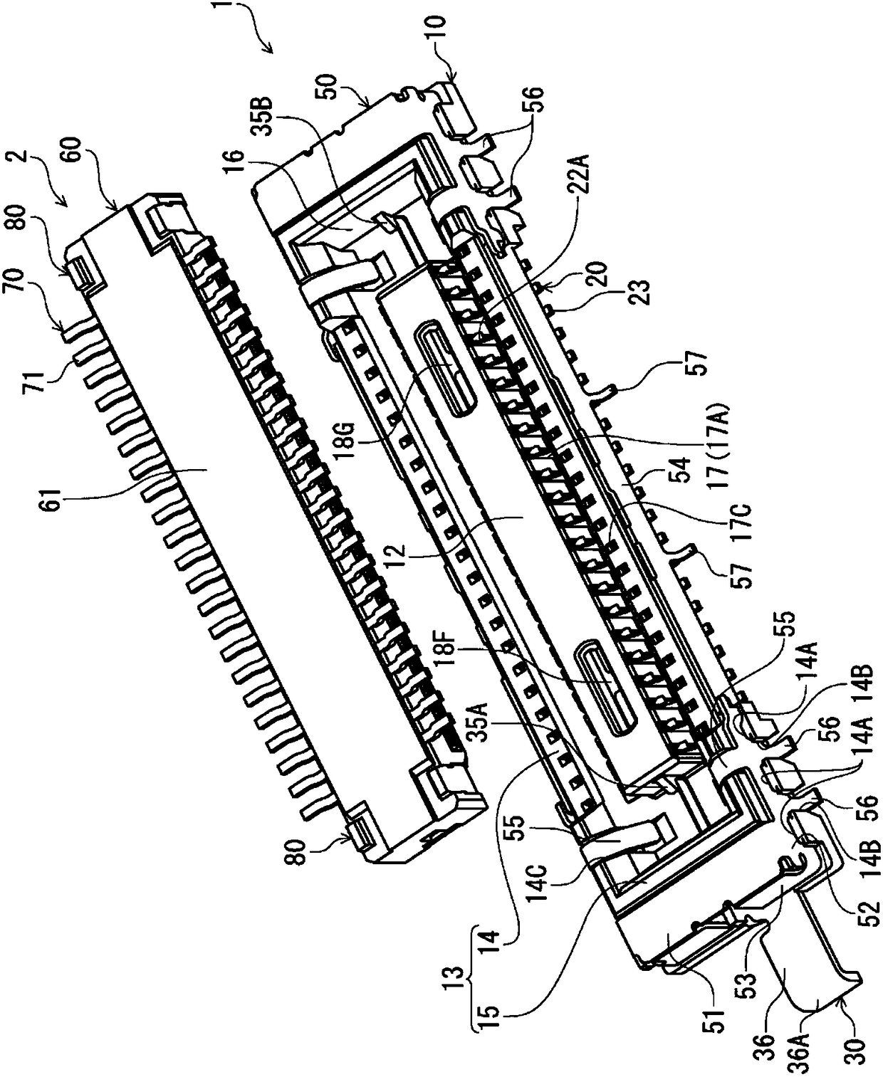
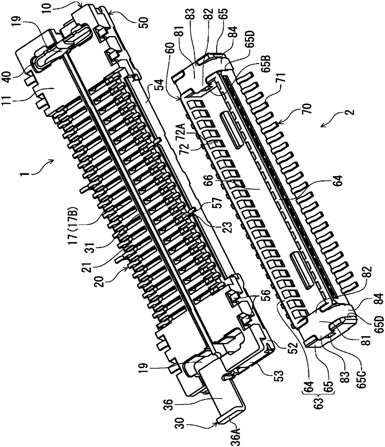
[0029] figure 1 It is a perspective view of the receptacle connector 1 according to this embodiment and the plug connector 2 fitted to the receptacle connector 1 from above, showing a state before the connectors are fitted. figure 2 is to make figure 1 The perspective view in which the receptacle connector 1 and the plug connector 2 are turned upside down and shown is a perspective view showing a posture in which the plug connectors are fitted from below.
[0030] The plug connector 2 of the present embodiment and the receptacle connector 1 which is the target connector of the plug connector 2 are electrical connectors for circuit boards respectively arranged on the mounting surfaces of different circuit boards (not shown), and constitute In the direction at right angles to the surface of each circuit board ( figure 1 The up and down direction in the middle) is used as the connector assembly in the plugging and unplugging direction. In this embodiment, the fitting directio...
no. 2 approach
[0100] In the first embodiment, the latching relief portions 82B, 83B of the latched portions 82, 83 of the latched member 80 provided on the receptacle connector 2 are formed as concave portions. Figure 10 The second embodiment shown in (A) differs from the first embodiment only in that the locking relief portions 182B, 183B are formed as holes penetrating through the locked portions 182 , 183 in the connector insertion / extraction direction. exist Figure 10 In (A), the part corresponding to each part of 1st Embodiment is shown in figure by attaching "100" to the code|symbol in 1st Embodiment. exist Figure 10 In (A), for convenience of description, only one end side portion in the terminal arrangement direction is shown.
[0101] as from Figure 10 As can be seen from (A), even if the locking relief portions 182B, 183B are formed as hole portions, it is possible to avoid contact between the front end portion 135A- 2 of the locking portion 135A of the receptacle connector...
no. 3 approach
[0103] In the first embodiment, the locked parts 82 and 83 of the locked piece 80 provided on the plug connector 2 are not bent but protruded from the base 81 in the terminal arrangement direction. However, in Figure 10 In the second embodiment shown in (B), at the boundary position between the locked parts 282 and 283 and the base part 281 toward the bottom wall 261 side of the plug-side housing 260 (in Figure 10 (B) differs from the first embodiment in that it is bent upward. exist Figure 10 In (B), for parts corresponding to the parts of the first embodiment, "200" is added to the reference numerals in the first embodiment and shown in the figure. exist Figure 10 In (B), for convenience of explanation, only one end side portion in the terminal arrangement direction is shown.
[0104] as from Figure 10 As can be seen in (B) of FIG. 3 , in the third embodiment, the locked portions 282 and 283 are formed by bending upward in the plate thickness direction. In the thir...
PUM
 Abstract
Description
Claims
Application Information