Hydraulic tensioner

a technology of hydraulic tensioner and tensioner body, which is applied in the direction of mechanical equipment, belts/chains/gearings, and ring/chain/gearings. it can solve the problems of affecting the biasing force of the traction member, faulty operation of the tensioner, and lost motion

Inactive Publication Date: 2005-06-16
SCHAEFFLER TECH AG & CO KG
View PDF12 Cites 25 Cited by
  • Summary
  • Abstract
  • Description
  • Claims
  • Application Information

AI Technical Summary

Benefits of technology

[0012] According to another feature of the present invention, a radially biased snap ring may be received in a groove of the piston for restricting a movement of the piston. The cylinder may hereby be formed with an internal shoulder which projects into a movement path of the snap ring to stop the movement of the piston. The reservoir in the form of a wavy or helical groove prevents an inadvertent locking of the snap ring.
[0013] Locking of the snap ring may also be avoided by forming the groove wall of the reservoir in the direction of the one-way valve with a circumferential chamfer or rounded transition zone. Thus, when inserting the piston into the cylinder, the radially biased snap ring may snap back into the reservoir but is automatically forced radially inwardly out of the reservoir, when the piston is pushed further into the cylinder.

Problems solved by technology

In the case of the tensioner, the pressure chamber decreases hereby in volume during the cool-down phase so that hydraulic fluid and air is being drawn in completely from a leakage gap located between the piston and the cylinder resulting in so-called lost motion.
Lost motion causes faulty operation of the tensioner because of the underpressure in the pressure chamber of the cylinder, when the internal combustion engine is at rest.
The underpressure is insufficient to open the one-way valve but, rather, draws the contained hydraulic fluid in the leakage gap.
Thus, the presence of trapped air in the pressure chamber during operation of the internal combustion engine, has an adverse effect on the operation of the tensioner because compressible air does not permit a defined position of the tensioner and thus of the tension roller, so that the biasing force of the traction member is adversely impacted as the tension roller is not properly supported upon the traction member.
In addition, noise develops and slippage of the traction member is experienced resulting in increased wear.

Method used


Image

  • Hydraulic tensioner
  • Hydraulic tensioner
  • Hydraulic tensioner

Examples


first embodiment

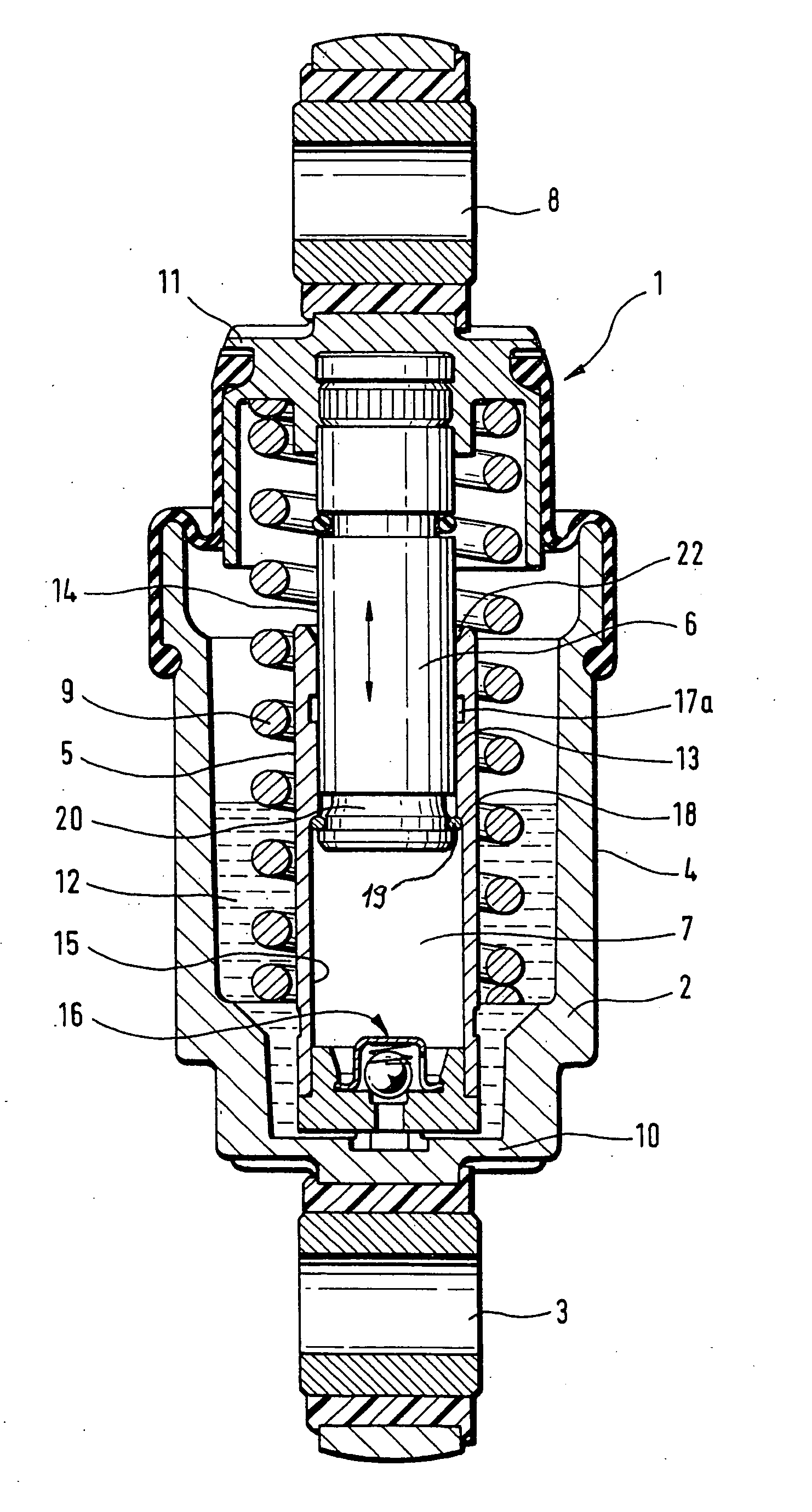
[0028] Turning now to the drawing, and in particular to FIG. 1, there is shown a longitudinal section of a hydraulic-mechanical tensioner according to the present invention, generally designated by reference numeral 1 and including a rotation-symmetric housing 2 of pot-shaped configuration. The housing 2 has one end connected to a fastening eye 3 which, for example, is swingably mounted to an internal combustion engine (not shown). Fitted centrally in the housing 2 radially inwards at a distance to an outer wall 4 of the housing 2 is a cylinder 5 which guides a piston 6 for longitudinal movement. A leakage gap 13 is defined between an outer surface area 14 of the piston 6 and an inside wall 15 of the cylinder 5. The piston 6 has one end surface to bound a pressure chamber 7 inside the cylinder 5 for hydraulic fluid, and another cylinder-distal end for connection to a fastening eye 8 which interacts directly or indirectly with a tension roller (not shown) for tensioning a traction me...

second embodiment

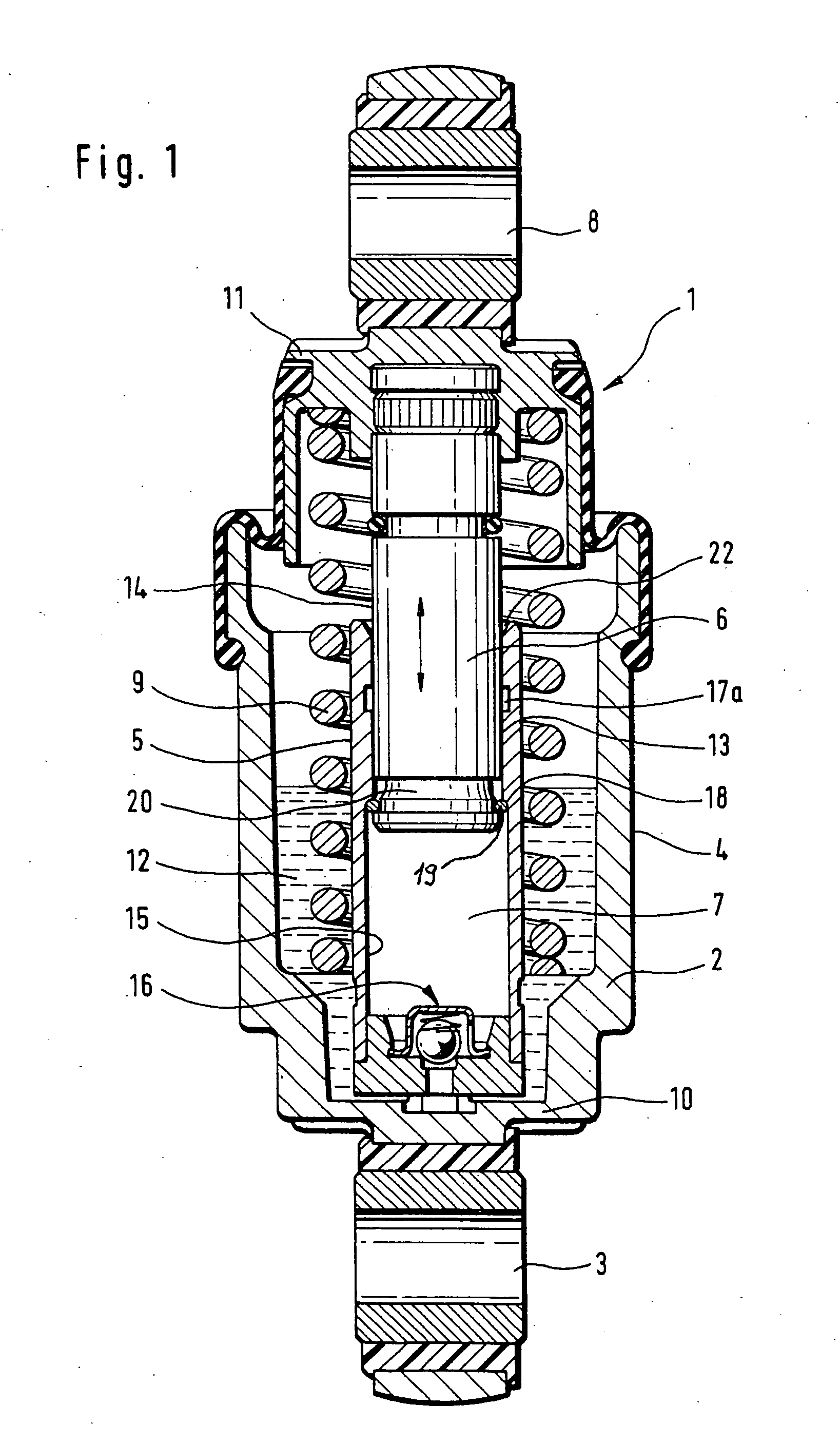
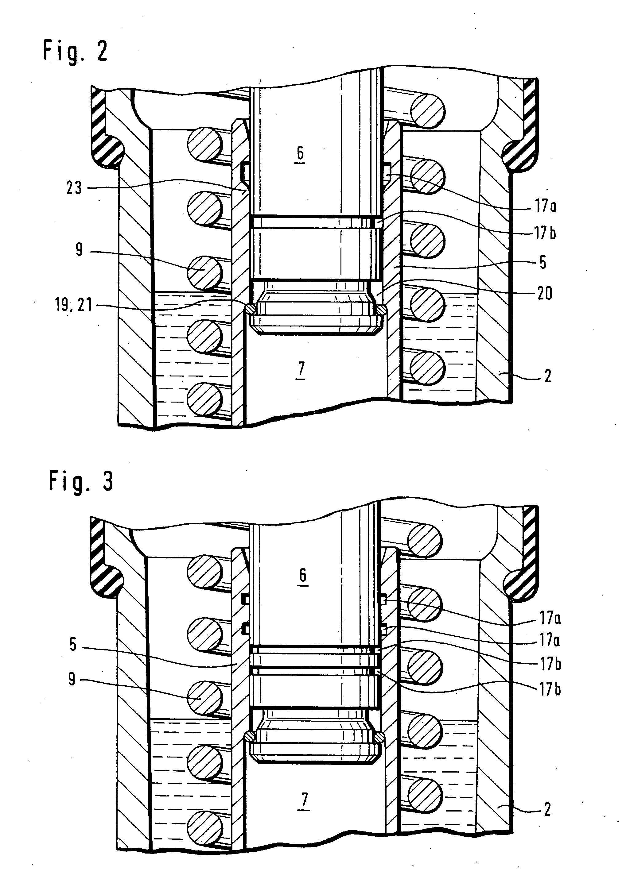
[0033] Turning now to FIG. 2, there is shown an enlarged detailed sectional view of a tensioner 1 according to the present invention. Parts corresponding with those in FIG. 1 are denoted by identical reference numerals and not explained again. The description below will center on the differences between the embodiments. In this embodiment, provision is made for a further reservoir 17b in the form of a circumferential groove in the piston 6 for hydraulic fluid. The provision of two reservoirs 17a, 17b increases the amount of hydraulic fluid in the leakage gap 13 to prevent a complete drainage, when hydraulic fluid is drawn by the underpressure into the pressure chamber 7. The reservoir 17a is configured with a slanted boundary surface which terminates in a rounded transition zone 23 to prevent the snap ring 19 from permanently snapping into the reservoir 17a, when the piston 6 is pushed into the cylinder 5.

[0034] A variation of the tensioner 1 is shown in FIG. 3 in which the reservoi...


PUM


Abstract

A tensioner for a traction drive includes a cylinder arranged in a housing at a distance to a housing wall to thereby define an interior space which contains hydraulic fluid. A piston is received in the cylinder for back-and-forth movement and bounds a pressure chamber containing hydraulic fluid. The piston has a cylinder-distal end which is operatively connected to a spring-biased tension roller supported on a traction member. Formed between the piston and the cylinder is a leakage gap, and a reservoir for hydraulic fluid is provided in an area of the leakage gap to prevent ingress of air into the pressure chamber, when the traction drive is at a rest.

Description

CROSS-REFERENCES TO RELATED APPLICATIONS [0001] This application is a continuation of prior filed copending PCT International application No. PCT / EP03 / 05288, filed May 20, 2003, which designated the United States and on which priority is claimed under 35 U.S.C. §120, the disclosure of which is hereby incorporated by reference, and which claims the priority of German Patent Application, Serial No. 102 22 752.7, filed May 23, 2002, pursuant to 35 U.S.C. 119(a)-(d).BACKGROUND OF THE INVENTION [0002] The present invention relates, in general, to a hydraulic-mechanical tensioner. [0003] Nothing in the following discussion of the state of the art is to be construed as an admission of prior art. [0004] German patent publication DE 41 24 500 A1 describes a hydraulic tensioner having a cylinder in which a piston is able to move back and forth and bounds a pressure chamber that contains hydraulic fluid. The pressure chamber is hereby separated from a circular-ring shaped interior space betwee...

Claims


Application Information

Patent Timeline
Patent Type & Authority Applications(United States)
IPC IPC(8): F16H7/08
CPCF16H7/0848F16H2007/0859F16H2007/0806
Inventor GRUNAU,, ARBOGASTBERTELSHOFER, THOMASKRATZ, EDUARDSCHAFER, CHRISTIANSCHAFER, HARALDJAGER, DIETMARORSI, MARCO
Owner SCHAEFFLER TECH AG & CO KG
Why Eureka
Try Eureka