Cable branch box distribution wall bushing and its connection assembly

A technology of cable branch boxes and wall bushings, applied in the direction of cable joints, etc., can solve the problems of inability to connect live, economic loss, large blackout range, etc., and achieve the effect of reducing the power outage range, improving power supply efficiency, and expanding the power outage range

Active Publication Date: 2017-04-12
STATE GRID CORP OF CHINA +2
View PDF6 Cites 0 Cited by
  • Summary
  • Abstract
  • Description
  • Claims
  • Application Information

AI Technical Summary

Problems solved by technology

The wall-piercing bushings of the two structures are linear structures, and the shunt lines between users are in series relationship. If there is a problem with the cable connection terminal of the previous user and needs to be removed and replaced, it will cause an open circuit at the back, that is to say, the entire Subsequent users are cut off, resulting in a large power outage and economic losses
In addition, when the current wall-piercing bushing is connected to the cable connection terminal through the intermediate joint, the intermediate joint and the cable connection terminal are separate parts connecting the conductor and the insulating part, and the connection needs to be carried out one by one. The stability after connection is poor. In addition, the power must be cut off when connecting. It cannot be connected with electricity, which will affect the reliability of power supply and cause economic losses.

Method used


Image

  • Cable branch box distribution wall bushing and its connection assembly
  • Cable branch box distribution wall bushing and its connection assembly
  • Cable branch box distribution wall bushing and its connection assembly

Examples


Embodiment 1

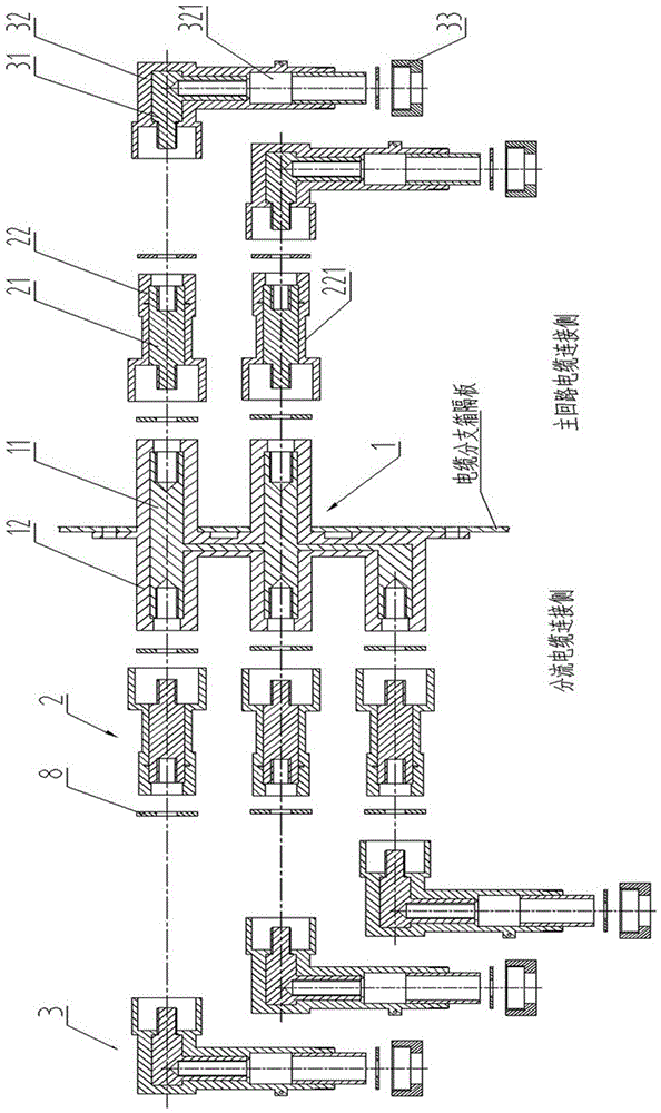
[0021] Preferred embodiment one, such as figure 1 As shown, this embodiment discloses a cable branch box shunt wall bushing and its connection assembly, including a type I shunt wall bushing 1, a type I butt joint 2 and an external thread head type L-shaped cable connection terminal 3 , the L-shaped cable connection terminal 3 is connected with the I-type shunt wall bushing 1 through the I-type butt joint 2 to form an assembly.

[0022] Type I shunt wall bushing 1 is an integral part of the conductive connecting body 11 and the hard insulating sleeve 12 embedded in the conductive connecting body 11. The side through the wall is the main circuit cable connection side, and the opposite side is the shunt cable connection side. ; The main circuit cable connection side of the conductive connecting body 11 is connected in parallel with two internal thread connection ends, and the shunt cable connection side is connected in parallel with three internal thread connection ends, and the...

Embodiment 2

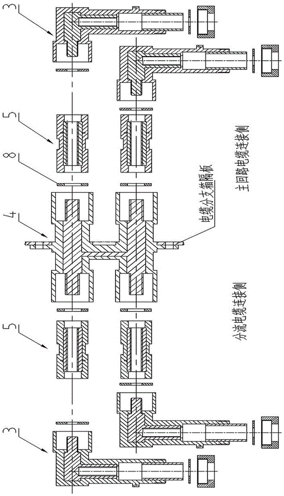
[0027] Preferred embodiment two, such as figure 2 As shown, the difference between this embodiment and the preferred embodiment 1 is that: the shunt wall bushing and the butt joint are respectively Type II shunt wall bushing 4 and Type II butt joint 5, and the Type II shunt wall bushing 4 and I The difference between Type II shunt wall bushing 1 is that two external thread connection ends of the coaxial center line are connected in parallel on both sides, so that Type II shunt wall bushing 4 forms an "I"-shaped structure, and its hard insulating sleeve The outer diameters of the two ends are larger than the outer diameters of the external thread connection ends of the conductive connecting body, so that the two ends of the hard insulating sleeve form an arc extinguishing chamber. The internal conductive butt joint body of type II butt joint 5 is an internal threaded pipe, and the corresponding external hard insulating sleeve is a straight tube type sleeve, and its two ends fo...

Embodiment 3

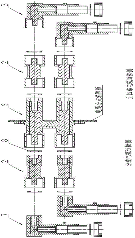
[0028] Preferred embodiment three, such as image 3 As shown, the difference between this embodiment and the preferred embodiment 1 is that: the shunt wall bushing and the butt joint are respectively type III shunt wall bushing 6 , and the L-shaped cable connection terminal also includes an internal thread hole type cable connection terminal 7 . The difference between type III shunt wall bushing 6 and type I shunt wall bushing 1 is that the main circuit cable connection side is connected with two internal thread connection ends in parallel, and the shunt cable connection side is connected with two external thread connection ends in parallel. The connection ends are coaxial with the center line, so that the type III split wall through-wall sleeve 6 forms an "I"-shaped structure. The difference between the internally threaded hole type cable connection terminal 7 and the externally threaded head type cable connection terminal is that the connection structure of the butt end is a...


PUM


Abstract

The invention discloses a cable branch box shunt wall-penetrating sleeve and a connecting combined member thereof. The cable branch box shunt wall-penetrating sleeve comprises a shunt wall-penetrating sleeve body, a docking joint and a cable connecting terminal, each of the shunt wall-penetrating sleeve body, the docking joint and the cable connecting terminal is an integral member composed of an inside electroconductive connecting body and a hard insulating body embedded in the inside electroconductive connecting body, and each cable connecting terminal is connected with the corresponding shunt wall-penetrating sleeve body integrally through the corresponding docking joint to form a combined member. Two threaded connecting ends connected with main loop wire incoming and outgoing cables are parallelly connected on a wall-penetrating side of each shunt wall-penetrating sleeve body, and multiple shunt cable threaded connecting ends communicated with the main loop cables at the same time for electroconduction are parallelly connected on an opposite side of each shunt wall-penetrating sleeve body. Shunt cables of users are in a parallel-connection state and mutually independent, and power receiving of other users is unaffected when the shunt cable connecting terminal of a certain user exits, so that power supply benefit is increased. An arc extinguishing chamber is arranged at a docking end of each of the shunt wall-penetrating sleeve bodies, the docking joints and the cable connecting terminals, only the docking joints need to be rotated during docking, and the users only contact with the hard insulating bodies during docking operation, so that the cable branch box shunt wall-penetrating sleeve is safe, quick and simple in process.

Description

technical field [0001] The invention relates to a cable branch box, in particular to a cable branch box branching wall bushing and a connecting assembly thereof. Background technique [0002] The current cable branch box uses the wedge-shaped screw-type wall-through bushing as the connection busbar, and the American-style cable branch box uses the screw-type wall-through bushing as the connecting busbar, and then realizes the cable branch through the connecting member connected with the wall-through bushing or transfer. The wall-piercing bushings of the two structures are linear structures, and the shunt lines between users are in series relationship. If there is a problem with the cable connection terminal of the previous user and needs to be removed and replaced, it will cause an open circuit at the back, that is to say, the entire The users in the back are all out of power, causing a larger power outage range and causing economic losses. In addition, when the current wa...

Claims


Application Information

Patent Timeline
Patent Type & Authority Patents(China)
IPC IPC(8): H02G15/10H02G15/18
CPCH02G15/10H02G15/18
Inventor 邓晓廉刘军志
Owner STATE GRID CORP OF CHINA
Why Eureka
Try Eureka