Capacitive element coupling in wireless power

一种电容性元件、无线充电的技术,应用在电气元件、电路、电路装置等方向,能够解决低功率传递效率等问题

Active Publication Date: 2015-09-09
INTEL CORP
View PDF6 Cites 6 Cited by
  • Summary
  • Abstract
  • Description
  • Claims
  • Application Information

AI Technical Summary

Problems solved by technology

In this case, detuning of the Tx coils leads to lower power transfer efficiency via the reactive magnetic field

Method used


Image

  • Capacitive element coupling in wireless power
  • Capacitive element coupling in wireless power
  • Capacitive element coupling in wireless power

Examples


example 1

[0055] The techniques described herein generally relate to wireless transmission and the creation of capacitive devices, such as capacitive elements, to couple with conductive components of under-charged devices (DUCs). For example, a DUC may have various conductive components, such as metal in the DUC's frame, that may decouple the intended inductive coupling between the DUC's transmit and receive coils.

example 2

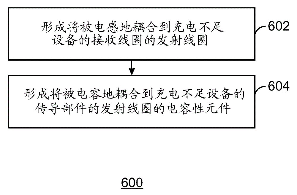
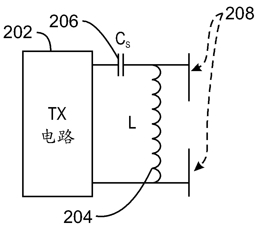
[0057] The techniques described herein may include a wireless charging component that includes a transmit coil and a capacitive device, such as a capacitive element to be coupled to a conductive component of an under-charged device (DUC). While the transmit coil will be inductively coupled to the DUC's receive coil, the capacitive device accommodates for inductive coupling disruption of the DUC's conductive component(s).

example 3

[0059] The techniques described herein may include wireless power receiving units for under-charged devices (DUCs). The receiving unit may include a receiving coil to be inductively coupled to the transmitting coil of the power transmitting unit. The receiving unit may comprise conductive components, such as a metal frame, or other computational components of the DUC to be capacitively coupled to the capacitive elements of the transmitting coil. The capacitive coupling between the conductive component and the capacitive element can be adjusted for breaks in the inductive coupling between the receive coil and the transmit coil that might otherwise occur due to the conductive element of the DUC.


PUM


Abstract

Techniques of capacitive coupling in a wireless power system are described herein. The techniques may include forming a transmitting coil to be inductively coupled to a receiving coil of a device under charge (DUC). The techniques may include forming a capacitive element of the transmitting coil to be capacitively coupled to a conductive component of the DUC.

Description

technical field [0001] The present disclosure generally relates to techniques for wireless charging. In particular, the present disclosure relates to capacitive coupling of a capacitive element to a conductive element of a device under charge. Background technique [0002] Magnetic resonance wireless charging can use magnetic coupling between a transmit (Tx) coil and a receive (Rx) coil. The Tx coil and the Rx coil may be coupled based on resonant inductive coupling, wherein power is transmitted from the Tx coil to the Rx coil by inductive coupling because each coil is tuned to resonate at a substantially similar frequency. In some cases, the Tx coil may be detuned when the magnetic field associated with the Tx coil interacts with conductive components of the receiving device, such as the metal chassis. For example, if an undercharged device has metal parts that interact with the Tx coil's magnetic field, eddy currents may be induced on the metal parts, where a reactive ma...

Claims


Application Information

Patent Timeline
Patent Type & Authority Applications(China)
IPC IPC(8): H02J17/00H01P5/08
CPCH02J5/005H02J50/05H02J50/12H02J50/40H02J50/60
Inventor S.杨J.科拉蒂科雷纳拉延S.卡斯图里J.罗森菲尔德M.汉南
Owner INTEL CORP
Why Eureka
Try Eureka