Battery tester

A battery testing and battery technology, applied in the direction of measuring devices, secondary batteries, components of electrical measuring instruments, etc.

Inactive Publication Date: 2004-03-17
MIDTRONICS
View PDF0 Cites 3 Cited by
  • Summary
  • Abstract
  • Description
  • Claims
  • Application Information

AI Technical Summary

Problems solved by technology

This measurement technique requires that the battery must be sufficiently charged to be able to supply current to the load

Method used


Image

  • Battery tester
  • Battery tester
  • Battery tester

Examples


Embodiment Construction

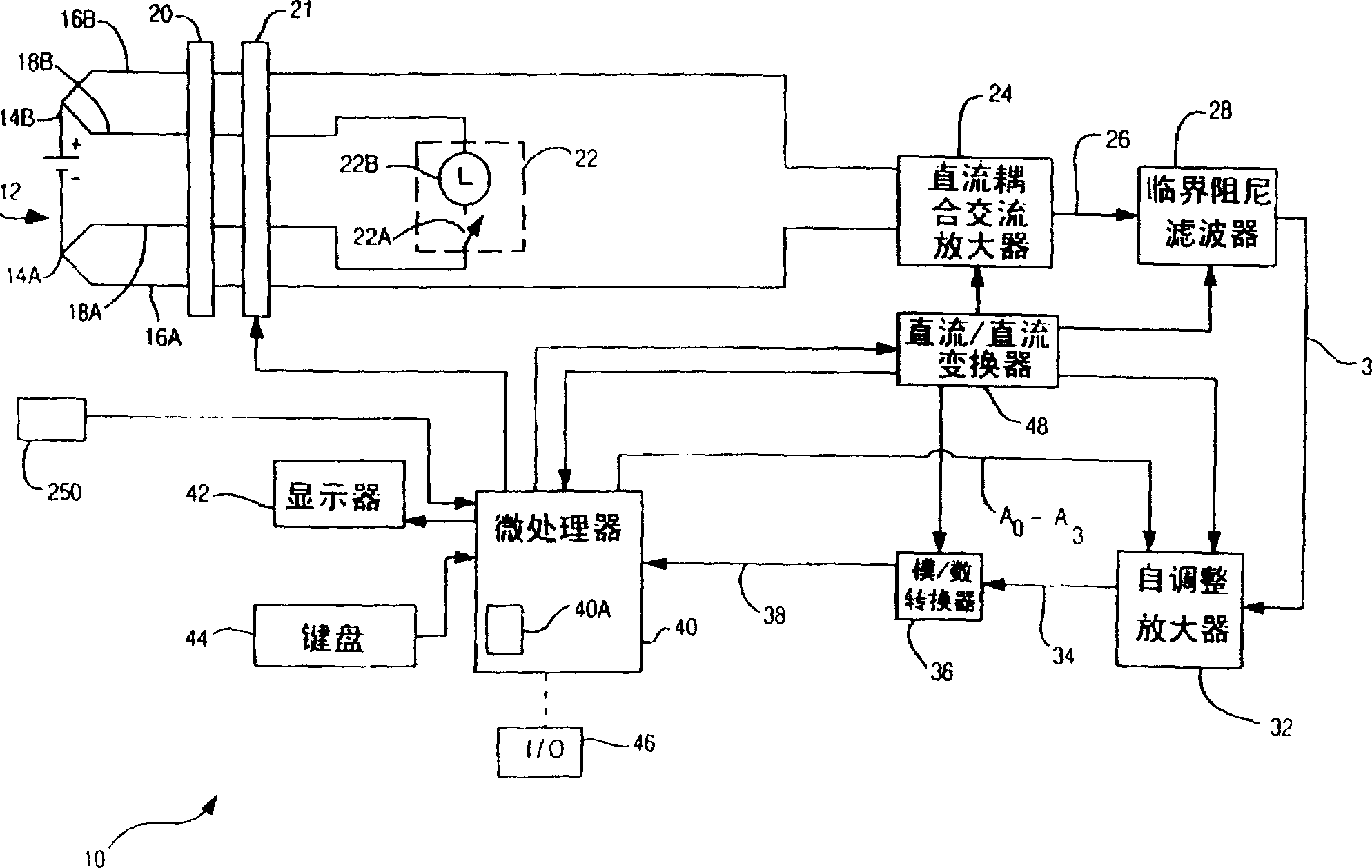
[0015] There is still a need to improve battery testing techniques, and the present invention is dedicated to providing a battery testing device in which current can flow into or out of the battery (i.e., a current exchanger) during testing, and the current is alternated according to the AC frequency of the power frequency. The present invention uses a large impedance load, and its advantages include:

[0016] It has the characteristics of resisting the change of contact resistance,

[0017] · High capacity - capable of testing 1-6 battery cells with a single circuit without damage,

[0018] The probing leads used to connect to the battery have a stable and / or predictable galvanic coupling effect,

[0019] According to the formula G (conductivity)=I / E, where I represents a substantially fixed current, so only the variable E needs to be measured, and it has a simple reciprocal relationship with G in quantity,

[0020] The number of electric fuses in the device can be reduced....


PUM


Abstract

An apparatus for electronically testing or monitoring the condition of a storage battery is provided. The apparatus includes an inductance cancellation circuit for use in a Kelvin probe of an electronic battery tester. The induction cancellation circuit reduces inductive coupling between leads of the Kelvin probe. The apparatus also includes a DC coupled AC amplifier for amplifying an AC response signal of an electronic battery tester. Other aspects include a critically damped band-pass filter a response signal, a DC to DC convertor isolation circuit, operator editable test criteria, a battery temperature sensing element, an automatically adjustable gain stage and the use of an internal reference standard for a self calibration.

Description

technical field [0001] The present invention relates to a battery testing technology, in particular, the invention relates to a battery testing device for testing a battery. Background technique [0002] Batteries have existed for a long time, such as lead-acid batteries that are widely used in motor vehicles or in industrial fields that require auxiliary power. Efforts have been made to understand the characteristics of such batteries, to study how they work, and especially to accurately test their condition, but the effort has proven to be far from satisfactory. The battery includes a plurality of battery cells electrically connected in series, and the voltage of each battery cell is about 2.1V. By connecting these battery cells in series, their voltages will be superimposed to form a total voltage. For example, taking a typical motor vehicle battery as an example, six battery cells are connected in series to form a total voltage, which is 12.6V when the battery is fully ...

Claims


Application Information

Patent Timeline
IPC IPC(8): G01R1/067G01R31/36H01M10/48
CPCG01R1/06711G01R31/3648G01R1/06788G01R31/3627G01R31/385
Inventor 凯文·I·贝特内斯
Owner MIDTRONICS
Why Eureka
Try Eureka