Multi-shaft unmanned aerial vehicle

An unmanned aerial vehicle and inter-axis technology, applied in the field of drones, can solve the problems of short airborne time of drones, and achieve the effect of reducing weight burden, reducing changes, and increasing airborne time

Active Publication Date: 2015-09-16
INST OF PHYSICS - CHINESE ACAD OF SCI
View PDF10 Cites 5 Cited by
  • Summary
  • Abstract
  • Description
  • Claims
  • Application Information

AI Technical Summary

Problems solved by technology

Limited to the current level of energy storage battery technology, the flight time of UAVs is generally short

Method used


Image

  • Multi-shaft unmanned aerial vehicle
  • Multi-shaft unmanned aerial vehicle
  • Multi-shaft unmanned aerial vehicle

Examples


Embodiment Construction

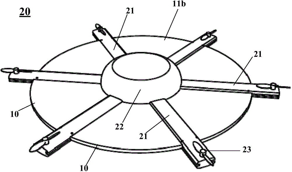
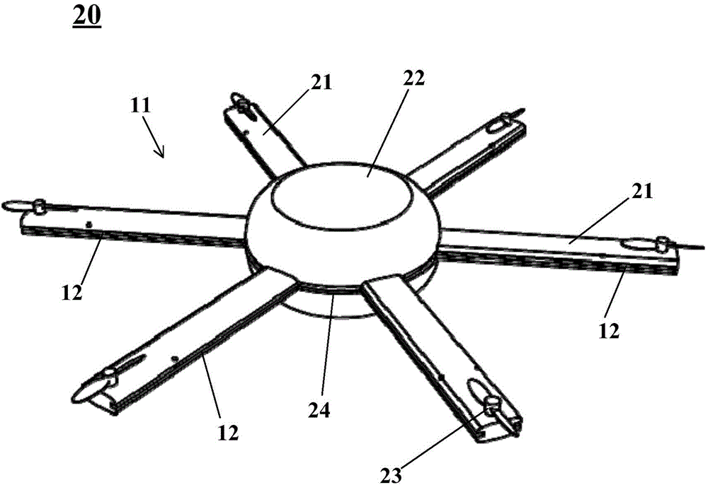
[0036] The multi-axis unmanned aerial vehicle 20 of the present invention includes a fuselage body, an axis, and a solar panel 10 . Wherein: the main body of the fuselage has a fuselage top 22 . The shafts 21 extend laterally outward from the main body of the fuselage, and the number is generally an even number. In one embodiment, 4 shafts are selected. figure 1 In the shown embodiment, six are selected. Such as figure 1 As shown, the multi-axis unmanned aerial vehicle 20 involved in the present invention includes six shafts 21 and a fuselage in the middle, the fuselage has a fuselage top 22 , and one end of each shaft 21 has a rotor 23 . The multi-axis unmanned aerial vehicle of the present invention forms a symmetrical structure as a whole. Any two adjacent shafts among the plurality of shafts are spaced apart from each other to form an inter-shaft gap 11 , thus the plurality of shafts form a corresponding plurality of inter-shaft gaps 11 . figure 2 There are six intera...


PUM


Abstract

The invention relates to the field of unmanned aerial vehicles, in particular to a multi-shaft unmanned aerial vehicle having solar panels. The multi-shaft unmanned aerial vehicle comprises a vehicle body, multiple shafts and multiple independent solar panels, wherein the multiple shafts outwards extend from the vehicle body in the transverse direction; any adjacent two shafts in the multiple shafts are spaced from each other to form an inter-shaft gap, therefore, multiple corresponding inter-shaft gaps are formed by the multiple shafts; the solar panels are used for converting solar energy to electric energy; and each solar panel is arranged in one corresponding inter-shaft gap in the multiple inter-shaft gaps to cover the corresponding inter-shaft gap. The solar panels are mounted on the multi-shaft unmanned aerial vehicle, can provide the electric energy to the multi-shaft unmanned aerial vehicle, and increase the hang time of the multi-shaft unmanned aerial vehicle. The solar panels are arranged in the inter-shaft gaps, so that idle spaces of the multi-shaft unmanned aerial vehicle are used.

Description

technical field [0001] The invention relates to the field of unmanned aerial vehicles, in particular to a multi-axis unmanned aerial vehicle with solar panels. Background technique [0002] The application of unmanned aerial vehicles is more and more extensive, and they are mostly powered by electric energy. Limited to the current level of energy storage battery technology, the flight time of UAVs is generally short. As shown in the multi-axis unmanned aerial vehicle disclosed in CN 201420834554.7, generally, the multi-axis unmanned aerial vehicle generally includes a fuselage and a shaft, a frame is installed at the lower part of the fuselage, and a rotor is installed at the far end of the shaft away from the fuselage. Contents of the invention [0003] An object of the present invention is to provide a technical solution for improving the airborne time of a multi-axis unmanned aerial vehicle. [0004] A further object of the present invention is to provide a technical ...

Claims


Application Information

Patent Timeline
Patent Type & Authority Applications(China)
IPC IPC(8): B64D27/26B64D27/24B64C27/12
CPCY02T50/50Y02T50/60
Inventor 孟庆波杨月勇徐余颛李冬梅罗艳红吴会觉
Owner INST OF PHYSICS - CHINESE ACAD OF SCI
Why Eureka
Try Eureka