Fuel injection system comprising a fuel-guiding component, a fuel injection valve and a connecting element

A fuel injection system and fuel injection valve technology, applied to fuel injection devices with noise reduction measures, low-pressure fuel injection, low-pressure fuel injection, etc., can solve problems such as noise, achieve noise reduction, improve connections, and realize assembly Effect

Inactive Publication Date: 2015-09-16
ROBERT BOSCH GMBH
View PDF8 Cites 0 Cited by
  • Summary
  • Abstract
  • Description
  • Claims
  • Application Information

AI Technical Summary

Problems solved by technology

[0003] The configuration of the fuel injection device known from DE 10 2005 020 380 A1 has the disadvantage that vibrations of the fuel injection valve can be transmitted to the connection stub via the snap ring
This leads to a strong noise development on the cylinder head and on the fuel distributor guide plate

Method used


Image

  • Fuel injection system comprising a fuel-guiding component, a fuel injection valve and a connecting element
  • Fuel injection system comprising a fuel-guiding component, a fuel injection valve and a connecting element
  • Fuel injection system comprising a fuel-guiding component, a fuel injection valve and a connecting element

Examples


Embodiment Construction

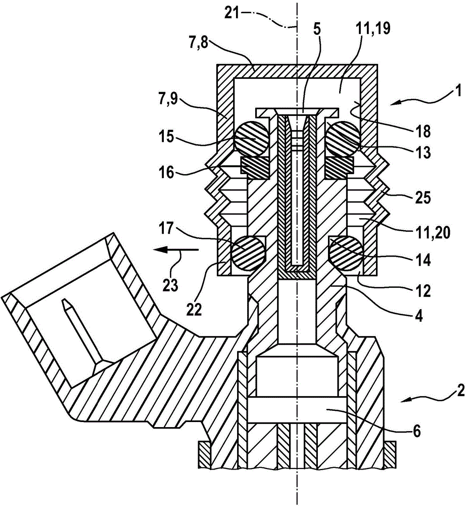
[0026] figure 1 A fuel injection system 3 ( Figure 5 ) connecting element 1 and fuel injection valve 2. The fuel injection system 3 can be used in particular for high-pressure injection in internal combustion engines. The fuel injection system 3 can be used in particular in hybrid compression external ignition internal combustion engines. The connecting element 1 is particularly suitable for such a fuel injection system 3 .

[0027] The fuel injection valve 2 of the fuel injection system 3 has a fuel connection 4 . At the inflow-side end 5 of the fuel connection 4 , fuel is guided into the fuel chamber 6 of the fuel injector 2 during operation.

[0028] The connecting element 1 has a base body 7 with an upper part 8 and a tubular part 9 . Appropriate inlet boreholes 10 are configured in the upper part 8 ( Figure 5 ) in order to guide the fuel into the receiving chamber 11 of the base body 7 of the connecting element 1 .

[0029] In the assembled state, the fuel connec...


PUM


Abstract

The invention relates to a connecting element (1) for fuel injection systems (3) used to connect a fuel injection valve (2) to a fuel-guiding component (45). A base body (7) comprising a receiving chamber (11) for a fuel nozzle (4) of the fuel injection valve (2) is provided. The fuel nozzle (4) which is arranged at least partially in the receiving chamber (11) is supported at least indirectly on the base body (7). Said fuel nozzle (4) is elastically supported on the base body (7) in a radial direction (23). The invention also relates to a fuel injection system (3) comprising said type of connecting element (1), the fuel injection valve (2) being connected to the components (45) by means of the connecting element (1).

Description

technical field [0001] The invention relates to a connecting element for a fuel injection system for connecting a fuel injection valve to a fuel guide component, and to a fuel injection system having such a connecting element. The invention relates in particular to the field of fuel injection systems for hybrid compression externally ignited internal combustion engines. Background technique [0002] A fuel injection device is known from DE 10 2005 020 380 A1, which is distinguished by an acoustically decoupled design. The known fuel injection device comprises a fuel injection valve, a receiving bore for the fuel injection valve in the cylinder head of the internal combustion engine and a fuel distributor line with a connection stub. The fuel injectors are introduced partially overlapping into the connection stubs. In one possible embodiment, a slotted snap ring is provided, which fits into the constricted section of the inlet stub of the fuel injection valve. For this pur...

Claims


Application Information

Patent Timeline
Patent Type & Authority Applications(China)
IPC IPC(8): F02M61/14F02M69/46
CPCF02M2200/09F02M2200/856F02M61/14F02M2200/16F02M2200/9015F02M69/462F02M55/004F02M55/02F02M61/167F16L27/107
Inventor M·菲舍尔M·诺尔普M·里默M·迈尔W·赖因哈特H-G·霍斯特A·格拉泽V·舍夫P·罗格勒J·赫尔曼A·雷瓦尔德
Owner ROBERT BOSCH GMBH
Why Eureka
Try Eureka