Fuse unit

A fuse and plug-in technology, which is applied in the field of fuse units, can solve the problems of poor operability and the inability to adjust the direction of the fuse installation hole, etc., and achieve the effect of improving visibility

Active Publication Date: 2015-09-16
YAZAKI CORP
View PDF4 Cites 2 Cited by
  • Summary
  • Abstract
  • Description
  • Claims
  • Application Information

AI Technical Summary

Problems solved by technology

In the conventional fuse unit, there is a problem that the direction of the fuse mounting hole itself cannot be adjusted when the fusible part is difficult to be recognized visually, so the adjustment can only be made by removing the blade type fuse. Confirmed, operability is poor

Method used


Image

  • Fuse unit
  • Fuse unit

Examples


Embodiment Construction

[0040] Hereinafter, preferred embodiments of the fuse unit of the present invention will be described in detail with reference to the drawings.

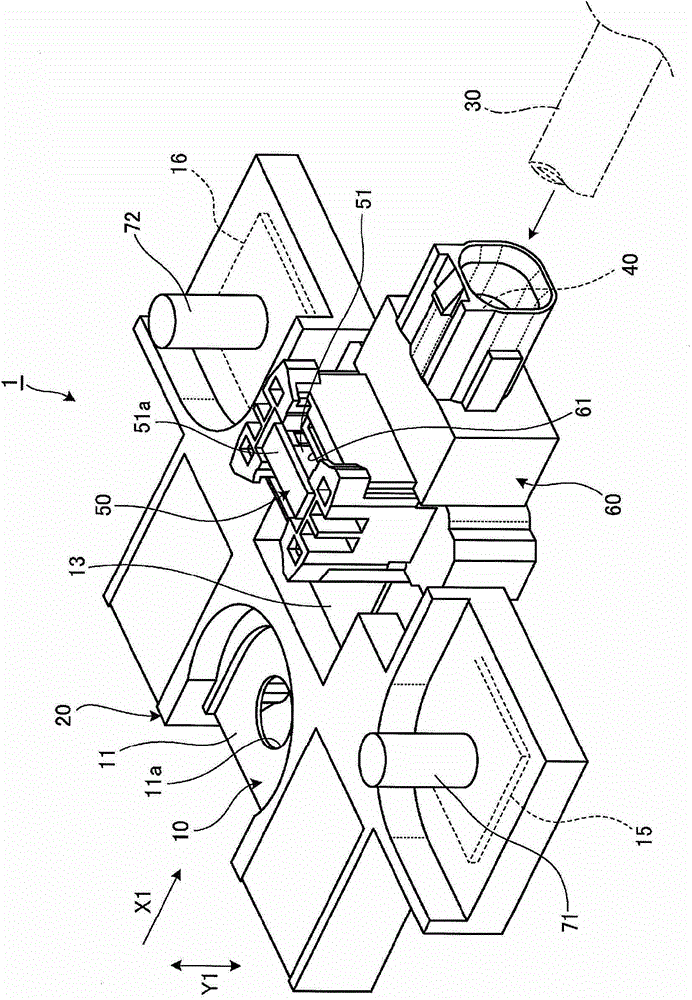
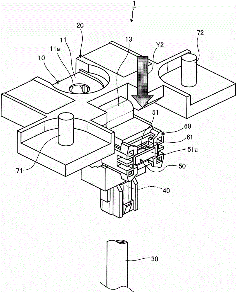
[0041] figure 1 is a perspective view of one embodiment of the fuse unit of the present invention, figure 2 Is to transfer the contact board part from figure 1 The shown state is a perspective view of a state where the fuse mounting hole is bent at a right angle and the orientation of the fuse mounting hole is changed by 90°.

[0042] The fuse unit 1 of this embodiment is a direct-connected fuse unit directly connected to a battery terminal (not shown) of a vehicle battery, and includes: a first terminal metal member 10 connected to a battery terminal; A housing 20 that accommodates and supports a part of the first terminal metal fitting 10; a second terminal metal fitting 40 that is connected to the wire harness 30 laid on the vehicle; and a resin-made second housing 60 that supports the first A part of the terminal metal fittin...


PUM


Abstract

A communication plate (13) which is bendable in the plate thickness direction and integrally formed with a first terminal metal fitting (10) which is connected to a battery terminal is exposed between a first housing (20) which is formed from resin and supports the first terminal metal fitting (10), and a second housing (60) which supports a second terminal metal fitting (40) to which a wire harness (30) is connected and has a fuse attachment hole (61); the orientation of the second housing (60) can be adjusted by bending the communication plate (13). Thereby, it is possible to not only increase the visibility of a blade fuse but to also improve the routing of a wire harness.

Description

technical field [0001] The present invention relates to a fuse unit for connecting an electric wire harness laid in a vehicle to a battery mounted on a vehicle via a blade fuse. Background technique [0002] As the above-mentioned fuse unit, a battery connection part connected to a battery, a harness connection part connected to a wire harness, and a fuse mounting hole for mounting a blade fuse are fixedly arranged on a resin case. Various proposals have been made (for example, refer to the following Patent Document 1). [0003] prior art literature [0004] patent documents [0005] Patent Document 1: Japanese Patent Laid-Open No. 2012-3904 Contents of the invention [0006] The technical problem that the present invention intends to solve [0007] Incidentally, the blade type fuse has a structure in which base ends of a pair of blades and a fusible portion connecting these base ends are housed in a resin case, and a pair of fuses are disposed on the top of the resin ...

Claims


Application Information

Patent Timeline
IPC IPC(8): H01H85/20H01H85/12H01H85/147H01H85/153
CPCH01H85/20H01H85/147H01H85/12H01H85/153H01H85/30H01H85/204
Inventor 加藤素文青木达也
Owner YAZAKI CORP
Why Eureka
Try Eureka