
Defogging device for central rearview mirror of automobile

A technology of a central rearview mirror and a defogging device, which is applied in the automotive field, can solve the problems that the driver cannot see the vehicle condition clearly, the central rearview mirror is water mist, and there is no central rearview mirror defogging, etc., so as to improve the wiping quality and improve the Efficiency and easy operation

Inactive Publication Date: 2017-02-22
HARBIN UNIV OF SCI & TECH
View PDF6 Cites 0 Cited by
  • Summary
  • Abstract
  • Description
  • Claims
  • Application Information

AI Technical Summary

Problems solved by technology

However, in winter or when the temperature is low, due to the high temperature of the gas exhaled by the occupants in the car, water mist is likely to appear in the central rearview mirror during driving, which makes the driver unable to see the situation behind the car clearly.
[0003] Currently, vehicles on the market have a defogging function that can defog the front windshield and side glass, but there is no direct defogging function for the central rearview mirror.
In the process of driving, the driver manually erases the water mist, which is a great driving hazard, especially when driving at high speed, it is more likely to cause traffic accidents.

Method used


Image

  • Defogging device for central rearview mirror of automobile
  • Defogging device for central rearview mirror of automobile
  • Defogging device for central rearview mirror of automobile

Examples


Embodiment Construction

[0018] In order to make the purpose, technical solution and advantages of the present invention more clear, the present invention is described below through specific embodiments shown in the accompanying drawings. It should be understood, however, that these descriptions are exemplary only and are not intended to limit the scope of the present invention. Also, in the following description, descriptions of well-known structures and techniques are omitted to avoid unnecessarily obscuring the concept of the present invention.

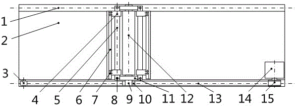
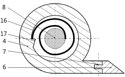
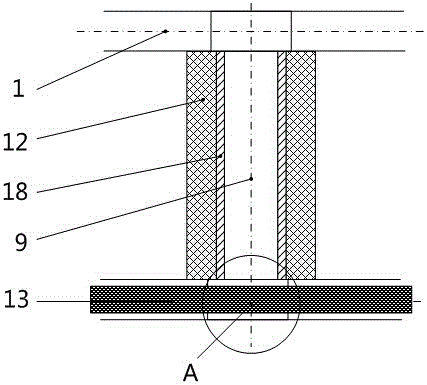
[0019] As shown in the figure, this specific embodiment adopts the following technical scheme: it includes guide rail 1, rearview mirror body 2, guide gear 3, fixed plate 4, scraper shaft 5, scraper 6, scraper fixing screw 7, scraper Shaft screw 8, input shaft 9, driven gear 10, connecting beam 11, rubbing wheel 12, gear belt 13, stepping motor 14, driving gear 15, coil spring 16, fixed seat 17, sleeve 18, positioning block 19, Spring 20, rearview mirror ...


PUM


Abstract

The invention discloses an automobile center rearview mirror defogging device, and relates to the technical field of automobiles. Guide rails are arranged on a rearview mirror body. A stepping motor is fixed to one side of the rearview mirror body. A driving gear is fixed to an output shaft of the stepping motor. A guide gear is fixed to the other side of the rearview mirror body. The guide gear is engaged with the driving gear through a gear belt. A driven gear is fixed to one side of an input shaft and engaged with the gear belt. A locating block is arranged outside the gear belt. A spring is arranged outside the locating block. A sleeve is arranged outside the input shaft. The outer side of the sleeve is fixedly connected with a friction wheel. The friction wheel and the sleeve can rotate around the input shaft. The upper end and the lower end of the input shaft are fixedly connected with connecting beams respectively. A scraper blade shaft is fixedly connected with the upper connecting beam and the lower connecting beam through scraper blade shaft screws. A coil spring is arranged between the scraper blade shaft and a fixed plate. One end of the coil spring is fixed to the scraper blade shaft, and the other end of the coil spring is fixed to a fixed seat of the fixed plate. A scraper blade is fixed to the fixed plate through a scraper blade fixing screw. The automobile center rearview mirror defogging device can wipe a mirror surface repeatedly during one-time motion, different wiping tools are combined, wiping quality can be improved, the mirror surface can be kept clean, and efficiency is improved.

Description

technical field [0001] The invention relates to a defogging device for a central rearview mirror of an automobile, which belongs to the technical field of automobiles. Background technique [0002] In the process of driving, because the central rearview mirror in the car can enlarge the driving and background directly behind the car, reduce the blind spots of the rearview mirrors on both sides, and make it easier for the driver to find the driving conditions behind the car, so as to decide to merge. Direction and speed therefore play an important role. However, in winter or when the temperature is low, due to the high temperature of the gas exhaled by the occupants in the car, water mist is likely to appear in the central rearview mirror during driving, causing the driver to be unable to see the vehicle conditions behind the car clearly. [0003] At present, vehicles on the market have a defogging function that can defog the front windshield and side glass, but there is no ...

Claims


Application Information

Patent Timeline
Patent Type & Authority Patents(China)
IPC IPC(8): B60S1/60
CPCB60S1/60
Inventor 姜金刚韩英帅彭博沈瑞超
Owner HARBIN UNIV OF SCI & TECH
Learn More