
A ventilation structure of a hard rock cutting reducer

A reducer, hard rock technology, applied in mechanical equipment, transmission parts, belts/chains/gears, etc., can solve the problems affecting gear and bearing lubrication and cooling, oil leakage, reduction of reducer oil capacity, etc. The effect of improving service life, increasing oil storage, and increasing oil level

Active Publication Date: 2017-04-05
DALIAN HUARUI HEAVY IND GRP CO LTD
View PDF6 Cites 0 Cited by
  • Summary
  • Abstract
  • Description
  • Claims
  • Application Information

AI Technical Summary

Problems solved by technology

If the oil level is low, the amount of oil in the reducer will decrease, which will affect the lubrication and cooling of the gears and bearings; It is also easy to leak oil from the breather cap

Method used


Image

  • A ventilation structure of a hard rock cutting reducer
  • A ventilation structure of a hard rock cutting reducer
  • A ventilation structure of a hard rock cutting reducer

Examples


Embodiment Construction

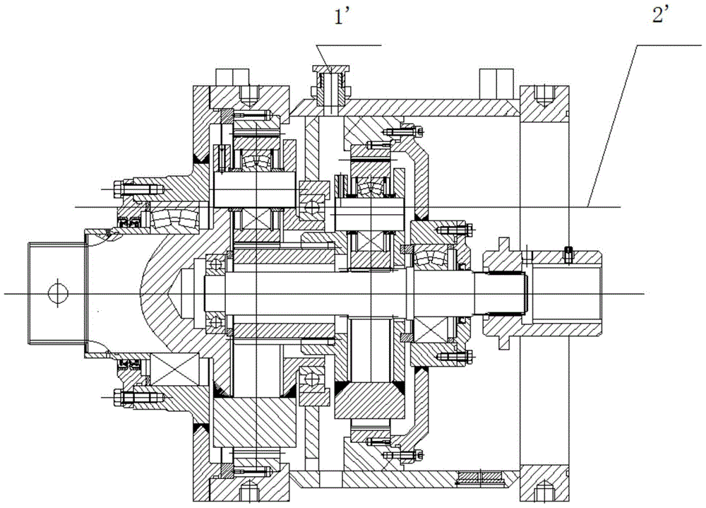
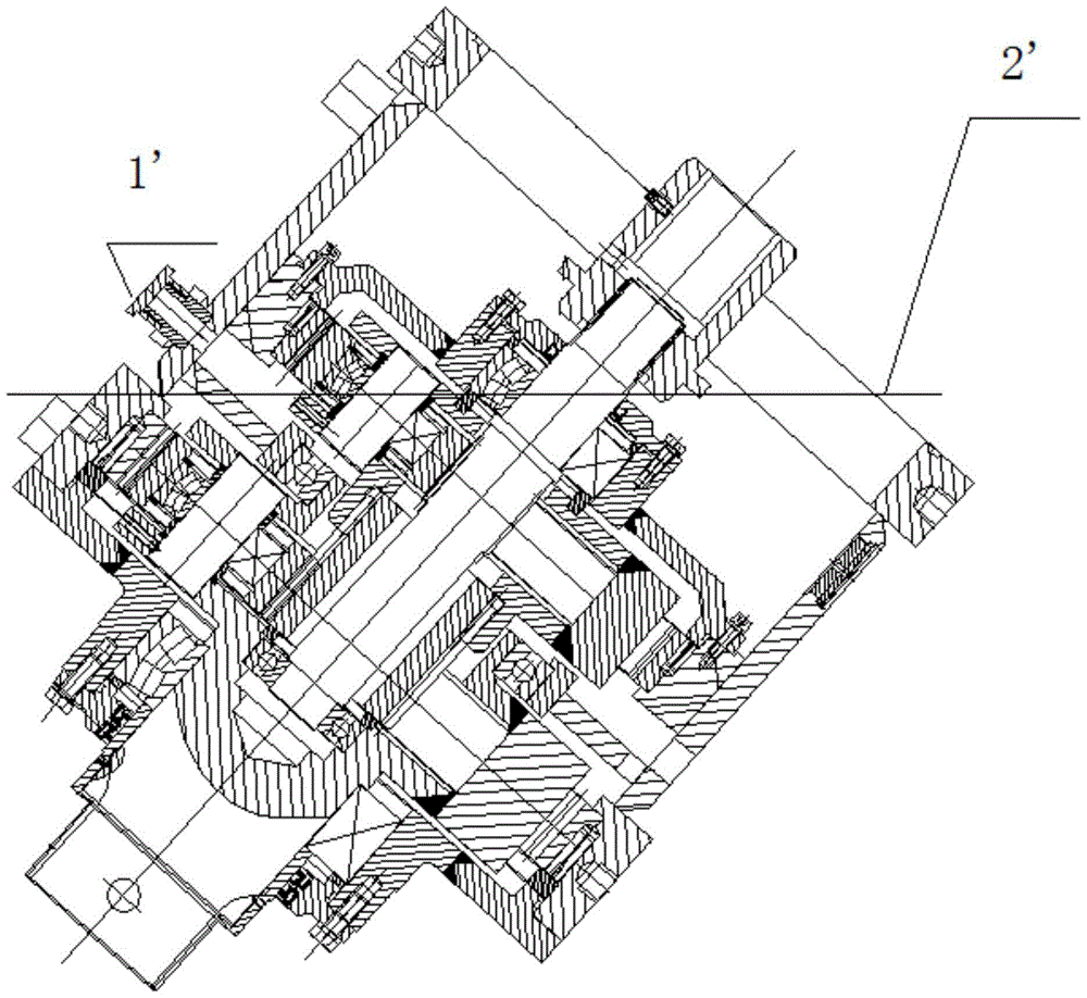
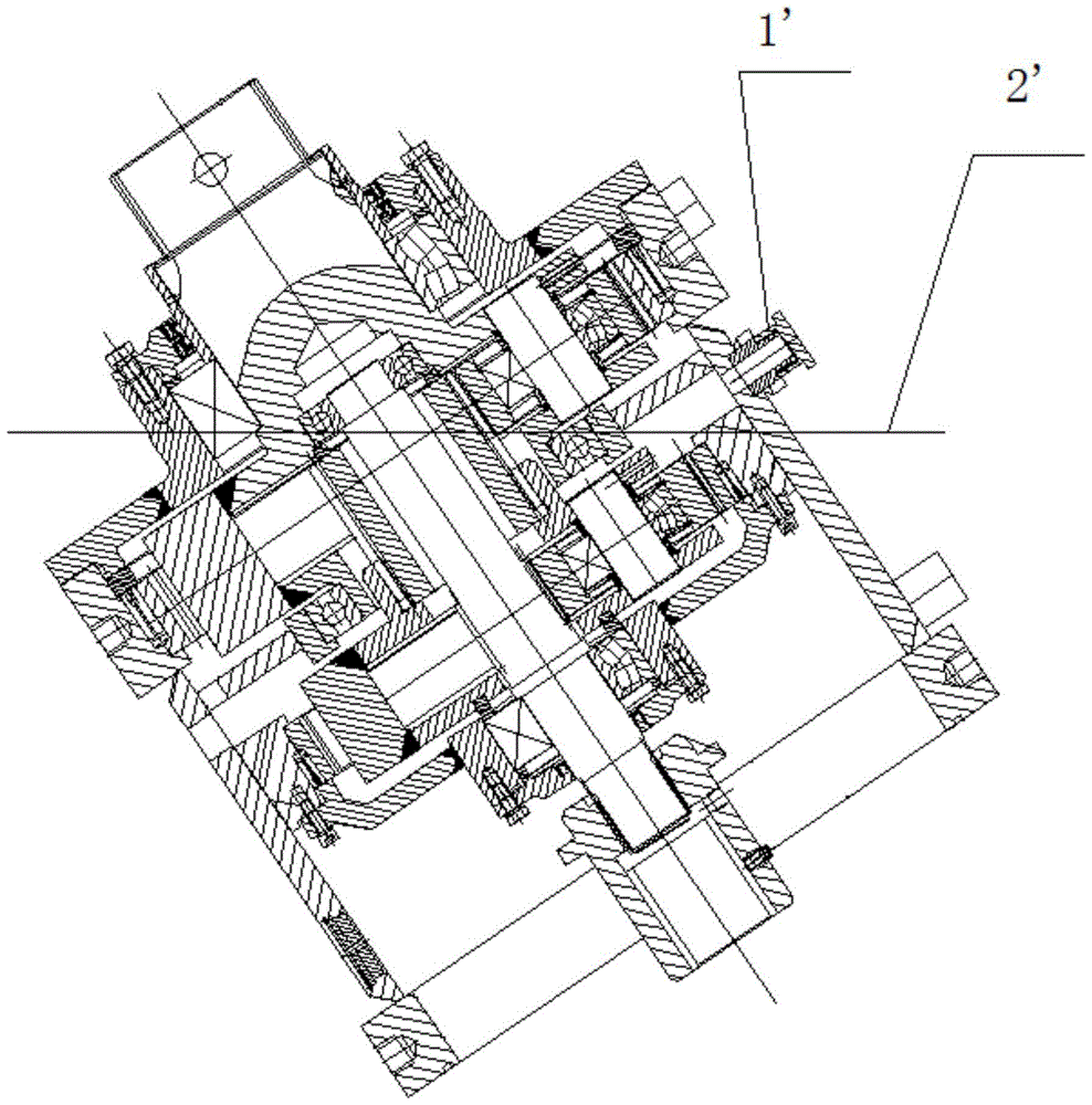
[0027] like Figure 4-Figure 7 As shown, a ventilating structure of a hard rock cutting reducer includes vent hole I1, vent hole II2, vent flow channel I3, vent flow channel II4 and vent cap 5, and the vent cap 5 is located in the housing of the reducer The middle part of the upper top 6, the vent hole I1 is located on the side of the inner wall of the upper top 6 close to the output end of the reducer, the axis of the vent hole I1 is perpendicular to the inner wall of the upper top 6, the One end of the vent hole I1 communicates with the housing of the reducer, and the other end of the vent hole I1 communicates with the vent cap 5 through the vent flow channel I3,

[0028] The vent hole II2 is located on the side of the inner wall of the upper top 6 close to the input end of the reducer, the axis of the vent hole II2 is perpendicular to the inner wall of the upper top 6, and one end of the vent hole II2 is connected to the input end of the reducer. The housing of the reducer...


PUM


Abstract

The invention discloses a ventilating structure for a hard rock cutting speed reducer. The ventilating structure comprises a ventilating hole I, a ventilating hole II, a ventilating flow pass I, a ventilating flow pass II and a ventilating cap, wherein the ventilating cap is located in the middle of the top of a shell of the speed reducer, one end of the ventilating hole I is communicated with the interior of the shell of the speed reducer, the other end of the ventilating hole I is communicated with the ventilating cap through the ventilating flow pass I, one end of the ventilating hole II is communicated with the interior of the shell of the speed reducer, and the other end of the ventilating hole II is communicated with the ventilating cap through the ventilating flow pass II. Due to the fact that the ventilating hole I and the ventilating hole II are away from the stirring centers of a gear and a planet carrier, by means of the damping effect of the ventilating hole I, the ventilating hole II, the ventilating flow pass I and the ventilating flow pass II, relative stability of oil level is guaranteed, oil level is increased, oil reserve is increased, gear and bearing lubricating and cooling effects are improved, and then the service life of the speed reducer is prolonged.

Description

technical field [0001] The invention relates to a ventilating structure, in particular to a ventilating structure of a hard rock cutting reducer. Background technique [0002] At present, a hard rock cutting reducer is installed on the front end of the working arm of the hard rock roadheader for the coal mine roadway. And with the movement of the working arm, the working angle is constantly changed, that is, sometimes it needs to be raised up to 55°, and sometimes it needs to be bent down to 48°. In this way, there is a contradiction between the oil level in the reducer and the installation position of the breather cap. If the oil level is low, the amount of oil in the reducer will decrease, which will affect the lubrication and cooling of the gears and bearings; It is also easy to leak oil from the breather cap. Therefore, the breather cap (1') of the existing hard rock cutting reducer will be arranged on the side close to the output end, and has a lower oil level line (...

Claims


Application Information

Patent Timeline
Patent Type & Authority Patents(China)
IPC IPC(8): F16H57/027
CPCF16H57/027
Inventor 王立军于天龙王欠欠王岩刘润泽
Owner DALIAN HUARUI HEAVY IND GRP CO LTD
Learn More