
Composite pipe oil tank device and application method

A composite pipe and oil tank technology, which is applied in the direction of oil supply tank device, fluid pressure actuator, servo motor, etc., can solve the problems of easy damage of sealing ring, high cost, complex structure, etc., and achieve long life, low cost, The effect of simple structure

Active Publication Date: 2018-04-06
CHINA NAT HEAVY MACHINERY RES INSTCO
View PDF9 Cites 0 Cited by
  • Summary
  • Abstract
  • Description
  • Claims
  • Application Information

AI Technical Summary

Problems solved by technology

[0004] The purpose of the present invention is to solve the problem of sealing the main hydraulic cylinder, high-pressure shut-off valve and other important parts caused by the high cost and complex structure of the existing oil tank device on the main hydraulic cylinder used in the composite pipe forming equipment or the oil quality of the fuel tank cannot be circulated. The problem of ring damage

Method used


Image

  • Composite pipe oil tank device and application method
  • Composite pipe oil tank device and application method

Examples


Embodiment 1

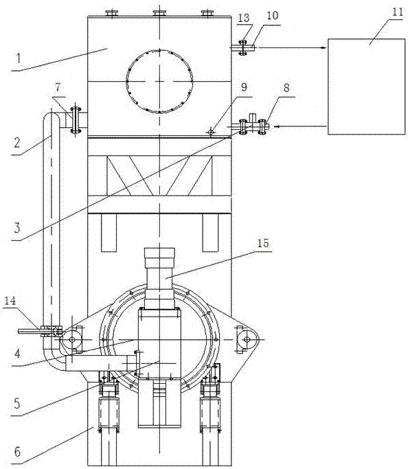
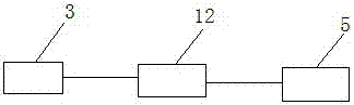
[0018] In order to solve the problem of the high cost and complex structure of the existing oil tank device on the main hydraulic cylinder used for composite pipe forming equipment or the easy damage of the sealing rings of important components such as the main hydraulic cylinder and high-pressure cut-off valve due to the oil quality of the oil tank cannot be circulated problem, this example provides figure 1 The composite pipe oil tank device shown includes a frame 6, the main hydraulic cylinder 4 is installed on the lower end of the frame 6, and the oil tank 1 is fixedly installed on the upper end of the frame 6, and the side of the oil tank 1 is provided with an oil suction port 7 and an oil discharge port 9 , the oil inlet 8 and the overflow port 10, the oil suction port 7 is connected to the oil delivery pipe 2, the oil delivery pipe 2 is connected to the inlet end of the cut-off on-off valve 5, and the outlet end of the cut-off on-off valve 5 is connected to the oil inlet...

Embodiment 2

[0026] On the basis of Embodiment 1, further, considering the effect of gravity, in order to allow the oil in the fuel tank 1 to be discharged conveniently, the overflow port 10 is opened at a position close to the top cover of the fuel tank 1, and the oil suction port 7, the exhaust port Both the oil port 9 and the oil inlet 8 are located below the overflow port 10 and close to the bottom cover of the oil tank 1 .

Embodiment 3

[0028] On the basis of Embodiment 1, the spool of the cut-off on-off valve 5 is equipped with a drive cylinder 15 that realizes the switch of the cut-off on-off valve 5, and the drive cylinder 15 replaces the valve rod to easily realize the switch on-off on-off valve 5; The diameter of the cut-off on-off valve 5 is 200mm, and the pressure is above 20MPa. The diameter of the cut-off on-off valve 5 purchased on the market is small, the flow rate is small, and the pressure is less than 20MPa, which does not meet the requirements of the composite pipe oil tank device provided by this embodiment. Requirements, therefore, a cut-off on-off valve 5 with a diameter of 200 mm is designed, the flow of the cut-off on-off valve 5 is increased by increasing the diameter, and the cut-off on-off valve 5 is under pressure above 20 MPa. In order to ensure the safety of the entire oil delivery process, the oil delivery pipe 2 is connected in series with a butterfly valve 14. When the main hydraul...


PUM


Abstract

The invention provides a composite pipe oil tank device applied to pressurizing of a main hydraulic cylinder of a bimetal pipe hydraulic forming machine. The composite pipe oil tank device comprises a rack. A main hydraulic cylinder is arranged at the lower end of the rack. An oil tank is arranged at the upper end of the rack and provided with an oil sucking opening, an oil discharging port, an oil inlet and an overflow port. The oil sucking opening is connected with a stop on-off valve through an oil conveying pipe, and the stop on-off valve is connected to the main hydraulic cylinder. The oil inlet is provided with a one-way electromagnetic one-way valve. The one-way electromagnetic one-way valve and the stop on-off valve are electrically connected with an industrial personal computer. According to the oil tank device, through an overflow, oil sucking and oil discharging loop, automatic circulation of oil of the oil tank is achieved through one one-way electromagnetic on-off valve, and the oil flows back to a hydraulic station in need. The one-way electromagnetic on-off valve only has the functions of a one-way valve, the stable oil level in the oil tank is guaranteed, and when oil products of the oil tank need to be replaced, the electromagnetic on-off valve is powered on, the oil products of the oil tank automatically flow back to a main hydraulic station, and the complex processes of oil pumping, discharging and the like during oil product replacing are avoided. The device has the beneficial effects of being simple in structure, low in using cost, long in service life and the like.

Description

technical field [0001] The invention belongs to the technical field of metallurgical equipment, in particular to the field of hydroforming of pipe equipment, and in particular relates to a composite pipe oil tank device and an application method. Background technique [0002] Due to the large diameter of the cylinder body and the large oil consumption per unit time, the main hydraulic cylinder of the composite pipe forming equipment adopts the direct supply method of the pump station. The direct supply of the pump station requires 4 to 8 oil pumps to work at the same time to meet the requirements. For this reason, two small-diameter oil cylinders are used to drive the main hydraulic cylinder forward, and the main hydraulic cylinder adopts the method of directly sucking oil from the upper oil tank to quickly move forward per unit time, and then uses the small flow supplementary method to complete the pressurization. [0003] The oil tank device on the main hydraulic cylinder ...

Claims


Application Information

Patent Timeline
Patent Type & Authority Patents(China)
IPC IPC(8): F15B11/16F15B1/26
CPCF15B1/26F15B11/16F15B2211/205
Inventor 刘邯涛张超王晓璋朱纪刚解通护
Owner CHINA NAT HEAVY MACHINERY RES INSTCO
Learn More