Panic lock

A technology of emergency locks and lock boxes, applied in building locks, locks with spring bolts, building fastening devices, etc., to achieve reliable locking effects

Inactive Publication Date: 2015-09-23
KARL FLIETHER GMBH & CO KG
View PDF7 Cites 0 Cited by
  • Summary
  • Abstract
  • Description
  • Claims
  • Application Information

AI Technical Summary

Problems solved by technology

[0006] A disadvantage of the constructions known from the prior art is that all mentioned constructions are only provided with a cartridge-based unlocking
Therefore, it is not possible to use it in emergency door locking devices that also have to be opened with a button control

Method used


Image

  • Panic lock
  • Panic lock
  • Panic lock

Examples


Embodiment Construction

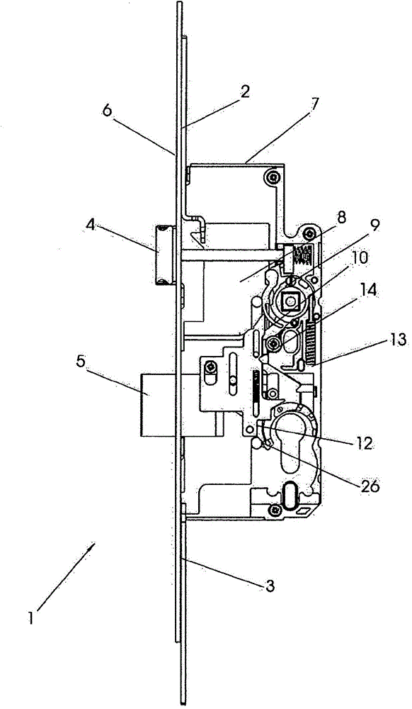
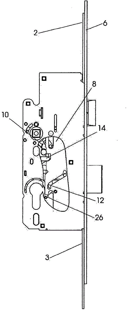
[0019] figure 1 Shown is the main lock box 1 of the multiple locking mechanism for actuating the bolt 4 and the main bolt or bolt 5 by means of transmission rods 2 , 3 protruding from the main lock box 1 . Other latch elements not shown here. These latch elements, not shown here, can likewise be latch elements supported in the secondary lock box or latch elements directly on the transmission rods 2, 3 and movable together with said transmission rods, said In the locked position, the latch element is assigned to engage the provided latch in a stationary manner in the latch engagement range. The drive rods 2 , 3 are guided displaceably on a collar rail 6 .

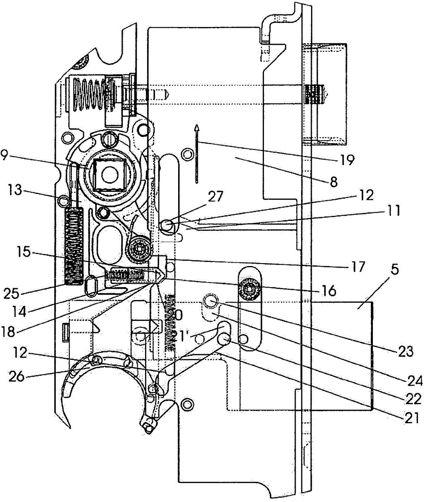
[0020] Inside the housing 7 of the master lock box 1 , the transmission rods 2 , 3 are drivingly connected via a transmission rod slide 8 and are simultaneously coupled with the master lock drive. Lock sleeve 9 has sleeve arm 10 ( figure 2 with 2a ), the sleeve arm stops on the corner 11 of the transmission rod slider ...


PUM


Abstract

The invention relates to a key- or pushbutton-actuable panic lock, in which a main lock case (1) is provided with a driving-rod slide (8) which is rigidly connected in terms of drive to driving rods (2, 3) and which is secured against displacement via a blocking device on the housing (7) of the main lock when the bolt (5) is extended, wherein the blocking device becomes inactivated by means of key-actuated unlocking. With the aim of specifying a lock with is actuable by pushbutton and which has a high level of security against the driving rods being pushed back, it is provided that the blocking device has a pawl (14) which is charged into the locking position thereof in the main lock case (1) by spring force and which can be forced back by means of a lever (12) which is actuable by a follower arm and a cylinder.

Description

technical field [0001] The invention relates to an emergency lock according to the preamble of claim 1 . Background technique [0002] Known from DE 3520862 C2 and DE 3537786 C2 is a lock construction solution in which the main lock box comprises a bolt and a dead bolt and a transmission rod slide which is connected to a shaft protruding from the housing of the main lock box. Transmission rod drive connection. The drive lever is assigned a secondary lock box and / or a latch element which can be moved into or out of the lock engagement by the drive lever. The transmission rod slide is provided with a locking device which prevents displacement of the transmission rod slide by the transmission rod in the locked position of the bolt. Thus, unlocking of the lock should be prevented if a potential thief tries to move the transmission rod or levers with the aid of a tool. Without a locking device, the pin of the main lock box and all other latch elements and / or secondary locks on...

Claims


Application Information

Patent Timeline
Patent Type & Authority Applications(China)
IPC IPC(8): E05B65/10E05C9/02E05B59/00
CPCE05B65/1086E05B59/00E05C9/026
Inventor H·扎拉尔瑟兹
Owner KARL FLIETHER GMBH & CO KG
Why Eureka
Try Eureka