

End mechanical self-locking hydraulic cylinder with buffering function
A hydraulic cylinder, self-locking technology, applied in the hydraulic field, can solve the problems of easy leakage of hydraulic oil, occupation, negative pressure effect, etc., to achieve the effect of buffering
- Summary
- Abstract
- Description
- Claims
- Application Information
AI Technical Summary
Problems solved by technology
Method used
Image

Examples
Embodiment Construction
[0023] Below in conjunction with accompanying drawing, the present invention is further described:
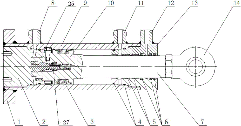
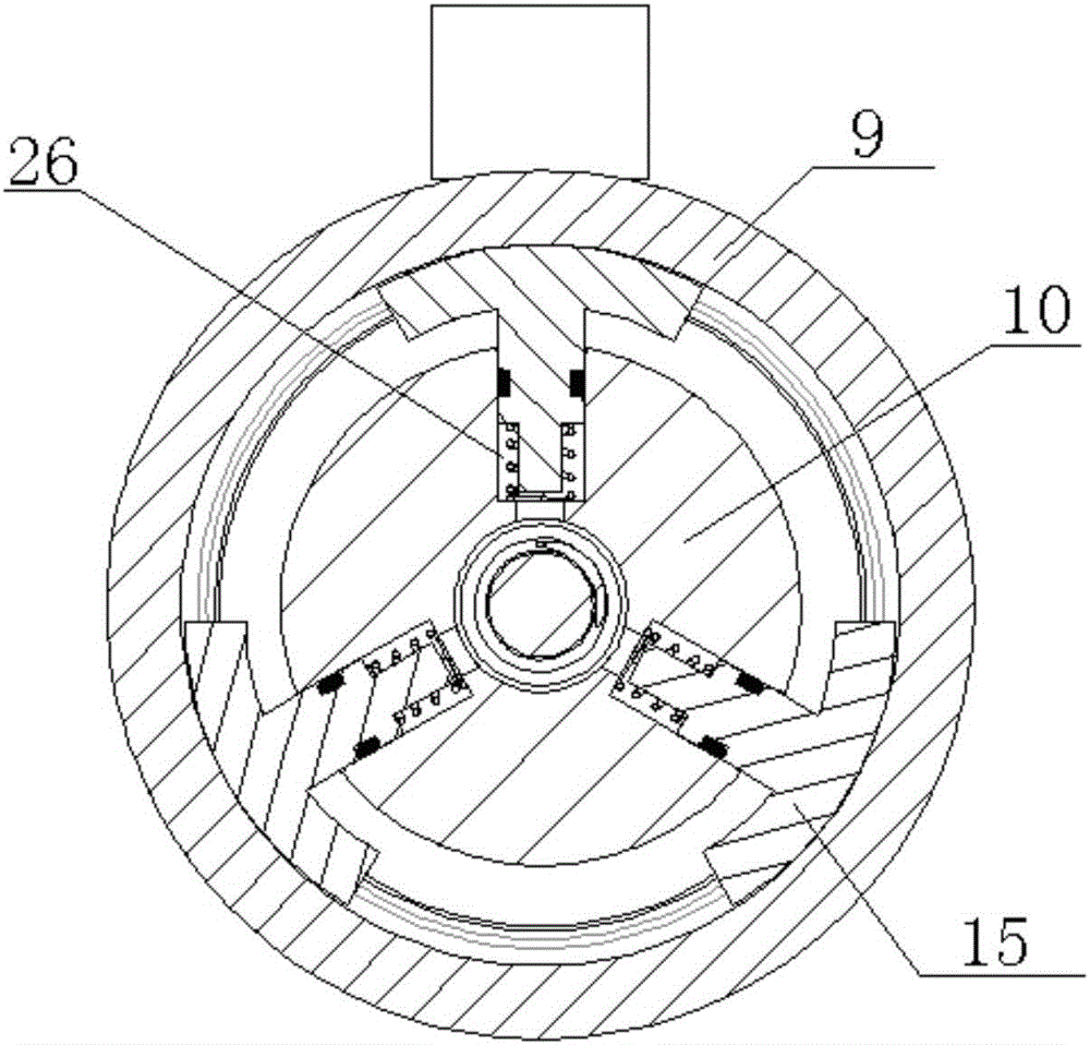
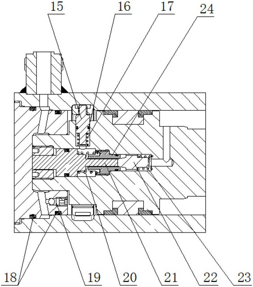
[0024] Such as figure 1 - As shown in -3, a kind of buffer end mechanical self-locking hydraulic cylinder includes a base 1, a cylinder 9 is installed on the base 1, a cylinder bottom 2 is installed at the tail end of the cylinder 9, and a cylinder bottom 2 is installed at the front end of the cylinder 9. The cylinder head 13, the base 1, the cylinder bottom 2, the cylinder barrel 9 and the cylinder head 13 are assembled into a hydraulic cylinder body. The cylinder barrel 9 is provided with a piston 10 near the cylinder bottom 2, and the front part of the piston 10 is connected and extended out of the cylinder head 13. The piston rod 7, the piston rod 7 is connected to the suspension ring 14, the tail end of the cylinder 9 is provided with a tail end oil port 8, the front end of the cylinder 9 is provided with a front end oil port 11, and the cylinder head 13 is provided with a...
PUM
 Abstract
Description
Claims
Application Information