Connector
A technology for connecting parts and connecting parts, applied in accessories, travel products, applications, etc., can solve problems such as poor operability, and achieve the effect of improving the clamping strength
- Summary
- Abstract
- Description
- Claims
- Application Information
AI Technical Summary
Problems solved by technology
Method used
Image

Examples
no. 1 approach
[0137] use Figure 1~Figure 8 The first embodiment of the present invention will be described.
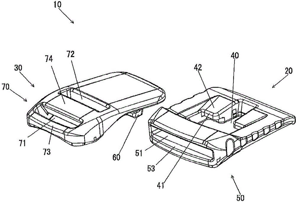
[0138] figure 1 Wherein, 10 indicates a connecting member, for example, used to connect the two ends of the belt to each other.
[0139] In addition, although the use of the connector 10 has been described as an example of a belt, it is not limited to this. For example, it can also be used for a fastener of a lid of a bag, and it is not limited to clothes, bags, and the like.
[0140] The connector 10 is formed by overlapping and connecting at least a part of the female member 20 and the male member 30 each having a plate shape.
[0141] (Female part 20)
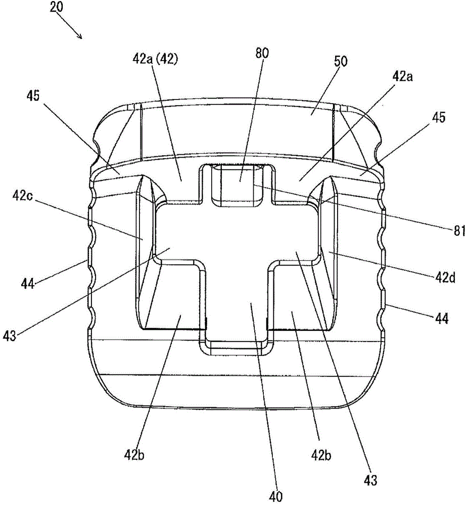
[0142] Such as figure 1 , image 3 and Figure 4 As shown, the female member 20 has a plate shape and overlaps with at least a part of the male member 30 described later and is connected to each other. The female member 20 is integrally molded with a thermoplastic resin having appropriate elasticity and rigidity, such as POM (polyacetal...
no. 2 approach
[0257] use Figure 9 ~ Figure 17 The second embodiment of the present invention will be described.
[0258] The first feature of this embodiment is that the strength is improved.
[0259] That is, as Figure 9~Figure 11 As shown, the planar shape of the opening 130 of the female component 110 is substantially square. And like Figure 13 As shown, the engaging protrusion 150 of the male member 110 is also made into a substantially rod shape and has sufficient strength.
[0260] According to this embodiment, the strength can be improved.
[0261] The second feature of this embodiment is that the appearance is changed.
[0262] That is, as Figure 9~Figure 11 As shown, the female component 110 is provided with a substantially V-shaped constricted portion 111. And like Figure 12 ~ Figure 16 As shown, the male member 120 is also provided with a through hole 121 penetrating in the thickness direction of the plate, so that the constricted portion 111 is invisible when the male member 120 a...
no. 3 approach
[0288] use Figure 18~Figure 29 The third embodiment of the present invention will be described.
[0289] The first feature of this embodiment is that Figure 18 and Figure 19 As shown, the shape of the elastic sheet 270 is changed.
[0290] That is, the elastic piece 270 is provided in a bridge shape spanning the opening 230 left and right. And like Figure 19 As shown, approximately the center of the elastic piece 270 is provided with a convex portion 271 that pushes the engaging protrusion 250 of the male member 220.
[0291] According to the elastic piece 270 of this embodiment, the elastic force can be improved.
[0292] The second feature of this embodiment is that Figure 18 As shown, a concave guide groove 233 is provided on the female component 210, such as Figure 23 As shown, the male member 220 is provided with a guide protrusion 253 fitted with the aforementioned guide groove 233.
[0293] That is, as Figure 21 As shown, the bottom surface 234 of the guide groove 233 slo...
PUM
 Abstract
Description
Claims
Application Information
 - R&D
- Intellectual Property
- Life Sciences
- Materials
- Tech Scout
- Unparalleled Data Quality
- Higher Quality Content
- 60% Fewer Hallucinations
Browse by: Latest US Patents, China's latest patents, Technical Efficacy Thesaurus, Application Domain, Technology Topic, Popular Technical Reports.
© 2025 PatSnap. All rights reserved.Legal|Privacy policy|Modern Slavery Act Transparency Statement|Sitemap|About US| Contact US: help@patsnap.com