Improved guiding and positioning pin for injection mold

A technology of guiding and positioning and injection molding, which is applied in the field of positioning between moving parts that need to be accurately guided. It can solve problems such as single action of guiding and positioning devices, flashing of injection molded parts, complex molds, etc., and achieves reliable fixation, smooth operation, and simplified interior. The effect of the structure

Inactive Publication Date: 2015-09-30
YONGGAO CO LTD +1
View PDF5 Cites 7 Cited by
  • Summary
  • Abstract
  • Description
  • Claims
  • Application Information

AI Technical Summary

Problems solved by technology

[0002] In the prior art, in the guiding and positioning between the moving parts of the injection mold, several methods are generally used, such as guide posts and guide sleeves, straight side locks (straight face locks), conical positioning pins, inclined positioning blocks, and conical beam barrels. Several guiding and positioning devices can only play a single role
However, in the actual injection mold, it is often encountered that the parting surface of the dynamic and fixed mold, the core pillow of the dynamic and fixed mold, etc. have too small slope. The contact surface such as the profile surface and the core pillow of the dynamic and fixed model touches first, and the parting surface of the movable and fixed mold, the core pillow of the dynamic and fixed model wears first, which is likely to cause flashing of the injection molded parts
If the above several guiding and positioning methods are used in combination, the mold will be complicated and the cost will be increased

Method used


Image

  • Improved guiding and positioning pin for injection mold
  • Improved guiding and positioning pin for injection mold

Examples


Embodiment Construction

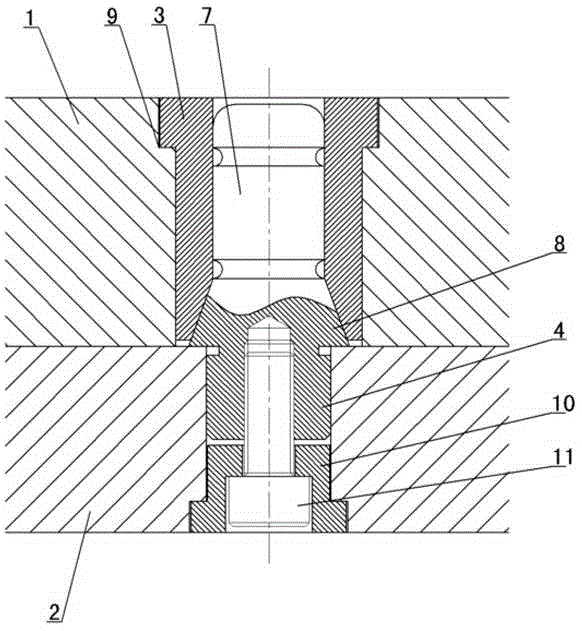
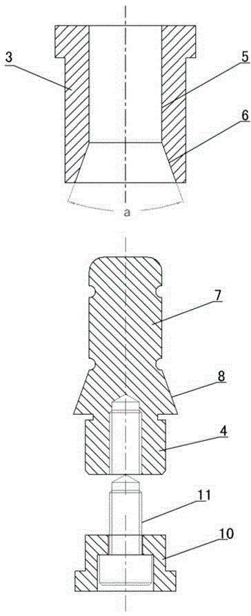
[0009] The invention relates to an improved guide and positioning pin for an injection mold, such as figure 1 , figure 2 As shown, it includes a mold cavity plate 1 and a core plate 2, a positioning sleeve 3 is installed in the cavity plate 1, a positioning pin 4 is installed in the core plate 2, and a straight face is set in the positioning sleeve 3. The guide hole 5 and the tapered lock hole 6, the positioning pin 4 is provided with a straight guide rod 7 and a tapered lock block 8, the straight guide rod 7 cooperates with the straight guide hole 5, the tapered lock block 8 and the tapered lock Hole 6 matches. When the injection mold is closed, the core plate 2 and the cavity plate 1 are closed, and the direct-facing guide rod 7 extends into the direct-facing guide hole 5, and the gap between the direct-facing guide rod 7 and the direct-facing guide hole 5 is generally 0-0.04mm, so , can precisely guide the closing of the core plate 2 and the cavity plate 1. When the cor...


PUM


Abstract

The invention discloses an improved guiding and positioning pin for an injection mold. The modified guiding and positioning pin comprises a mold cavity plate and a core plate, wherein a positioning sleeve is mounted in the cavity plate, and a positioning pin is mounted in the core plate; a straight surface guiding hole and a conical surface locking hole are formed in the positioning sleeve, a straight surface guiding rod and a conical surface locking block are arranged on the positioning pin, the straight surface guiding rod and the straight surface guiding hole are matched, and the conical surface locking block and the conical surface locking hole are matched. Through the adoption of the scheme disclosed by the invention, two functions of straight surface guiding and conical surface positioning are combined into one component, so that double functions of guiding and positioning between two moving components of the injection mold are realized, the modified guiding and positioning pin is simple in structure, convenient to process and low in cost, the internal structure of the mold is simplified, and the investment cost of the mold is reduced.

Description

technical field [0001] The invention relates to an improved guide and positioning pin of an injection mold, which is mainly used for positioning between moving parts requiring precise guidance. Background technique [0002] In the prior art, in the guiding and positioning between the moving parts of the injection mold, several methods are generally used, such as guide posts and guide sleeves, straight side locks (straight face locks), conical positioning pins, inclined positioning blocks, and conical beam barrels. Several guide positioning devices can only play a single role. However, in actual injection molds, it is often encountered that the parting surface of the dynamic and fixed mold, the core pillow of the dynamic and fixed mold, etc. have too small slopes. The contact surface such as the profile surface and the core pillow of the fixed and dynamic model contacts first, and the parting surface of the fixed and movable mold, the core pillow of the fixed and dynamic mod...

Claims


Application Information

Patent Timeline
Patent Type & Authority Applications(China)
IPC IPC(8): B29C45/36
CPCB29C45/36B29C2045/363
Inventor 卢震宇冀雄段洪文陈爱平周正杰曾富财
Owner YONGGAO CO LTD
Why Eureka
Try Eureka