Short Arc Type Flash Lamp And Light Source Device

A flash lamp and short arc technology, used in discharge lamps, gas discharge lamps, high pressure discharge lamps, etc., can solve the problems of reducing and increasing the concave reflector's condensing efficiency, and achieve the effect of simplified internal structure and high lamp start-up performance.

Inactive Publication Date: 2015-09-02
USHIO DENKI KK
View PDF6 Cites 2 Cited by
  • Summary
  • Abstract
  • Description
  • Claims
  • Application Information

AI Technical Summary

Problems solved by technology

As a result, there is a problem that when configuring the light source device, the lamp insertion opening of the concave reflector needs to be enlarged, and the light collecting efficiency of the concave reflector decreases.

Method used


Image

  • Short Arc Type Flash Lamp And Light Source Device
  • Short Arc Type Flash Lamp And Light Source Device
  • Short Arc Type Flash Lamp And Light Source Device

Examples


no. 1 approach

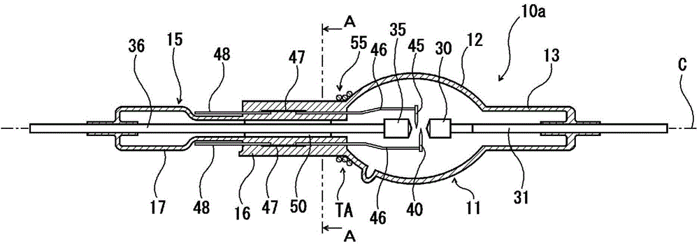
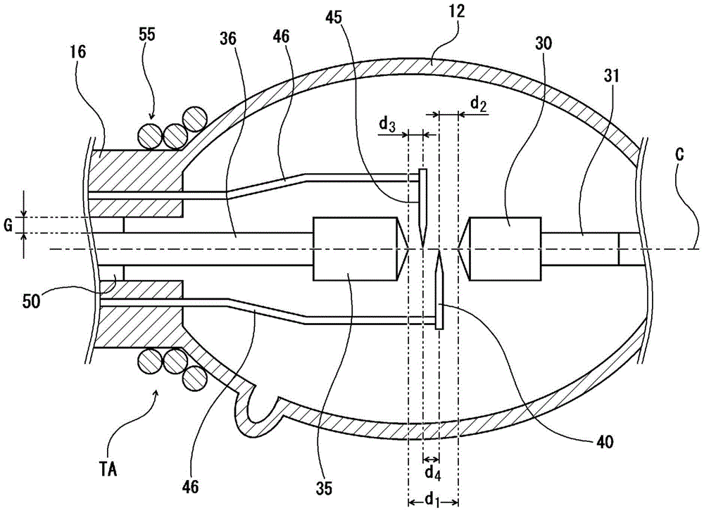
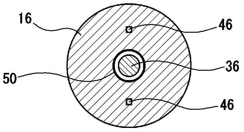
[0035] figure 1 It is a cross-sectional view along the tube axis direction showing a schematic configuration of an example of the short-arc strobe lamp according to the first embodiment of the present invention. figure 2 yes means figure 1 An enlarged partial view of the main part of the short-arc flash shown. image 3 yes figure 1 The A-A line sectional view in.

[0036] The short-arc strobe (hereinafter simply referred to as "strobe") 10a according to the first embodiment is a so-called double-end (both ends sealed) strobe, and has a bulb 11 equipped with a The light-emitting space has, for example, an ellipse-shaped light-emitting tube part 12, a first sealing tube part 13 that is continuous with one end of the light-emitting tube part 12 and extends outward along the tube axis direction, and a first sealing tube part 13 that is continuous with the other end of the light-emitting tube part 12 and extends along the tube axis. The second sealing pipe portion 15 extend...

no. 2 approach

[0081] Figure 6 It is a cross-sectional view along the tube axis direction showing a schematic configuration of an example of the short-arc strobe lamp according to the second embodiment of the present invention.

[0082] Regarding the flash 10b, except in Figure 1 to Figure 3 In the strobe lamp 10 a according to the first embodiment shown, the thickness of the external trigger arrangement area TA where the external trigger 55 is arranged in the second sealed tube part 15 of the bulb 11 is greater than the thickness of the starting auxiliary electrode sealing part 16 . This strobe 10b has the same structure as the strobe 10a according to the first embodiment except for a small structure.

[0083] In this flash lamp 10b, the starting auxiliary electrode sealing portion 16 of the second sealing tube portion 15 in the bulb 11 is continuous with one end of the arc tube portion 12 via the preliminary discharge space forming portion 18, and one end surface of the starting auxilia...

no. 3 approach

[0089] Figure 7 It is a cross-sectional view along the tube axis direction showing a schematic configuration of an example of the short-arc strobe lamp according to the third embodiment of the present invention.

[0090] Regarding the flash 10c, except in Figure 6 In the strobe lamp 10b according to the second embodiment shown, the outer diameter of the preliminary discharge space forming portion 18 in the second sealed tube portion 15 of the bulb 11 is smaller than the outer diameter of the starting auxiliary electrode sealing portion 16. The strobe 10c has the same configuration as the strobe 10b according to the second embodiment.

[0091] In this strobe lamp 10c, the preliminary discharge space forming part 18 constituting the external trigger arrangement area TA in the second sealed tube part 15 of the bulb 11 is reduced in diameter radially inward over the entire circumferential range, and the preliminary discharge The size (width) of the gap between the inner periph...


PUM


Abstract

Disclosed herein are a short arc type flash lamp having high lamp starting performance and capable of reducing the diameter of its seal tube part, and a light source device thereof. The flash lamp has an electrode shaft of one of the main electrodes, and an electrode shaft of the other of the main electrodes and leads for starting auxiliary electrodes which are respectively led out from the second seal tube part, and an external trigger is disposed in a state in which it extends in the circumferential direction on the outer peripheral surface of one end side region of the second seal tube part. The light source device is structured by a concave reflection mirror disposed on the second seal tube part side of the flash lamp in a state in which a focal point of the concave reflection mirror coincides with a luminous point of the flash lamp.

Description

technical field [0001] The present invention relates to a short-arc strobe and a light source device provided with the short-arc strobe. Background technique [0002] Currently, as a light source for annealing by photoheating in semiconductor manufacturing, thin film transistor manufacturing, etc., for example, a long-arc flash lamp is used. [0003] In addition, it is desired to condense light or form parallel light with, for example, a concave reflector or other optical components in a flashlight. In such a case, it is necessary to reduce the distance between electrodes and form a point light source. [0004] Figure 9 It is a cross-sectional view along the tube axis direction showing an outline of the structure of an example of a conventional short-arc strobe. [0005] This short-arc strobe includes a bulb 70 having a substantially ellipsoidal arc tube portion 71 and sealing tube portions 72 and 75 respectively continuous with both ends of the arc tube portion 71 . In t...

Claims


Application Information

Patent Timeline
Patent Type & Authority Applications(China)
IPC IPC(8): H01J61/36H01J61/54
CPCH01J61/90H01J61/025H01J61/073H01J61/366H01J61/545H01J61/30H01J61/547H01J61/86H01J61/0732Y02W30/82
Inventor 加濑征彦平石隆之
Owner USHIO DENKI KK
Why Eureka
Try Eureka